
How Things are Intended to Work: Capturing Functional Knowledge in Device Design
Proceedings of the Thirteenth International Joint Conference on Artificial Intelligence. Qualitative Reasoning and Naive Physics. Pages 1516-1521.
© 1993 International Joint Conferences on Artificial Intelligence
Abstract
When designing a device, the final product of the design process is usually considered to be a physical specification of a device. However, the design of the causal mechanism underlying the physical specification, i.e. how the device is intended to work to achieve its function, is a product just as important as the physical specification, if not more. Capturing this knowledge of causal mechanism is necessary in order to understand the physical specification of the device as well as to evaluate and refine the specifications during the design process. Despite the importance of such knowledge, existing CAD tools do not support its explicit representation or manipulation. We describe a design support system under development in which knowledge of both the causal mechanism and the physical structure of a device being designed is explicitly represented and manipulated. The system allows the designer to provide functional specifications at various levels of abstraction in a language called CFRL (Causal Functional Representation Language). The CFRL specification acquired from the user enables the system to evaluate the physical specification as it is being developed in order to provide useful feedback to the designer. Furthermore, functional specifications provide an important basis for recording the engineer's design rationale.
- [Bradshaw and Young, 1991] J.A. Bradshaw and R.M. Young. Evaluating Design Using Knowledge of Purpose and Knowledge of Structure. IEEE Expert, April1991.
- [Chandrasekaran et al, 1993] B. Chandrasekaran, Ashok Goel and Yumi Iwasaki. Functional Representation as Design Rationale. IEEE Computer, 26(1): 48-56, January 1993.
- [Fischer et al, 1991] G. Fischer et al. Making Argumentation Serve Design. Journal of Human Computer Interaction, 6(3-4):393-419, 1991.
- [Franke, 1991] David W. Franke. Deriving and Using Descriptions of Purpose. IEEE Expert, April1991.
- [Gero, 1990] John Gero. Design Prototypes: A Knowledge Representation Schema for Design. AI Magazine, 11(4):26- 36, winter 1990.
- [Gautier and Gruber, 1993] Patrice Gautier and Thomas Gruber. Generating Explanations of Devices Behavior Using Compositional Modeling and Causal Ordering. In Proceedings of the Eleventh National Conference on Artificial Intelligence, Washington D.C., July 1993. American Association for Artificial Intelligence.
- [Iwasaki and Chandrasekaran, 1992] Yumi Iwasaki and B. Chandrasekaran. Design Verification through Function and Behavior-Oriented Representations: Bridging the gap between Function and Behavior. In Proceedings of the Second International Conference on Artificial Intelligence in Design, Pittsburgh, 1992. 1522 Qualitative Reasoning and Naive Physics [Iwasaki and Levy, 1993] Yumi Iwasaki and Alon Levy. Automated Model Selection for Simulation. In Procedings of the Seventh International Workshop on Qualitative Reasoning about Physical Systems, Orcas Island, WA, 1993.
- [Iwasaki and Low, 1991] Yumi Iwasaki and Che Meng Low. Model Generation and Simulation of Device Behavior with Continuous and Discrete Change. Technical Repon KSL-91-69, Dept. of Computer Science, Stanford University, 1991.
- [Klein, 1993] Mark Klein. Capturing Design Rationale in Concurrent Engineering Teams. IEEE Computer, 26(1):39- 47, 1993. .
- [Lee and Lai, 1991] J. Lee and K-Y. Lai. What's in a Design Rationale?. Journal of Human Computer Interaction, 6(3- 4):250-280, 1993.
- [Lockheed, 1984] Lockheed Missiles and Space Company. SMM Systems Procedure for Electrical Power Subsystem. doc #D889545A, SE-23, Vol. 3, 1984.
- Macaulay, 1988)
- David Macaulay. The Way Things Work. Houghton Mifflin Company, Boston, 1988.
- [Sembugamoorthy and Chandrasekaran, 1986] V. Sembugamoorthy and B. Chandrasekaran. Functional Representation of Devices and Compilation of Diagnostic Problem-Solving Systems.
- Kolodner J.L. and Riesbeck C.K., editors. Experience, Memory and Reasoning. Lawrence Erlbaum Associates, Hillsdale, NJ, 1986.
- Vescovi et al, 1993) Marcos Vescovi, Yumi Iwasaki, Richard Fikes and B. Chandrasekaran. CFRL: A Language for Specifying the Causal Functionality of Engineered Devices. In Proceedings of the Eleventh National Conference on Artificial Intelligence, Washington D.C., July 1993. American Association for Artificial Intelligence.
References were extracted automatically from the PDF and may contain errors.
Full text extracted automatically from the PDF; figures, tables and equations may differ. The PDF is the version of record.
1 Introduction
Understanding how a device works requires understanding the causal sequences of events that achieve the function of the device. Books on how man-made or natural "devices" work are filled with drawings of structures of devices accompanied by explanations such as the following example of an aneroid barometer [Macaulay, 1988]:
*The research by the first three authors is supported in part by the Advanced Research Projects Agency, ARPA Order 8607, monitored by NASA Ames Research Center under grant NAG 2581, and by NASA Ames Research Center under grant NCC 2537. Chandrasekaran's research is supported by the Advanced Research Projects Agency by means of AFOSR contract F-4962089-C-0110 and AFOSR grant 89-0250.
Laboratory for AI Research The Ohio State University 217 B, Bolz Hall, 2036 Neil Avenue Columbus, OH 43210-1277
As the air pressure falls , the spring pulls the side of the capsule outward. The arm rises, causing the rocking bar to slacken the chain. The hairspring unwinds, moving the pointer counter-clockwise until the chain is pulled taut.
Such explanations refer to parts of the structure and describe how it works in terms of the sequence of causal interactions among the parts that lead to the desired result. In other words, such explanations and the drawings they accompany describe the device structure along with the conceptual causal mechanism underlying the structure.
When designing a deviCe, the final product of the design process is usually considered to be a physical specification of a device. However, the design of the causal mechanism underlying the physical specification is a product just as important as the physical specification, if not more. Gero makes this point clear in his model of the design process shown in Figure 1 [Gero, 1990]. Gero argues that, except in a trivial design problem, a structure is not generated directly from the requirements. In his model of design synthesis, a specification of the expected behavior is generated from the requirements 1, and the physical structure is generated from the expected behavior. In that model, the expected behavior corresponds to the expected causal sequence of interactions, i.e. how the device is to work.
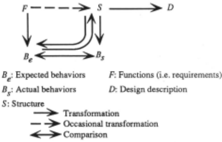
1 Gero calls the requirements "functions" and denotes them with F in Figure 1. However, in this paper, we will use the term "requirements" to avoid confusion since we consider the term "function" to also include what he calls "expected behavior".
Capturing this knowledge of how the device is to work to achieve its function is important in order to understand the physical specification of the device as well as to evaluate and refine the specifications during the design process. One can even view the design of a conceptual causal mechanism as driving the generation of a physical specification. Despite the importance of such knowledge, existing CAD tools do not facilitate its explicit representation or manipulation.
According to Gero, the design process involves the following types of activities to manipulate the four types of information shown in Figure 1.
- Formulation: Transforming requirements to expected behavior. F -+Be
- Synthesis: Transforming expected behavior to a structure. Be --+ S.
- Analysis: Deriving behavior from a structure. S --+ B s
- Evaluation: Comparing the predicted and expected behaviors. Bs HBe
- Reformulation: Reformulating the expected behavior based on evaluation results. (S, Bs)--+ Be
- Description: Producing a description of the designed structure. S --+ D
A comprehensive design support system needs to support multiple iterations through all those steps, since any non trivial design problem will require many such iterations. We are extending our Device Modeling Environment (DME) system [Iwasaki and Low, 1991] to provide such support and to enable explicit representation and manipulation of knowledge of both the causal mechanism and the physical structure of a device being designed. The system allows the designer to provide functional specifications at various levels of abstraction in a language called CFRL (Causal Functional Representation Language). The CFRL specification acquired from the user enables the system to evaluate the physical specification as it is being developed in order to provide useful feedback to the designer. Furthermore, functional specifications provide an important basis for recording the engineer's design rationale.
This paper describes the use of CFRL in the extended version of DME. We first describe CFRL and then illustrate the capabilities of the new system by presenting a hypothetical design scenario. We conclude with a discussion of our current status and related work.
2 CFRL
CFRL is a formalism we have developed for representing the functions and expected behavior of a device. It allows one to represent knowledge of the functions that a device is intended to achieve and also of the sequence of causal interactions among its components that lead to achievement of the functions. In CFRL, the function of the overall device is described first and the behavior of each component is described in terms of how it contributes to the function.
We have provided the language with a well-defined semantics in terms of a behavior representation widely used in model-based qualitative simulation [Vescovi et al, 1993], and we have used CFRL as the basis for a functional verification program which determines whether a behavior achieves an intended function.
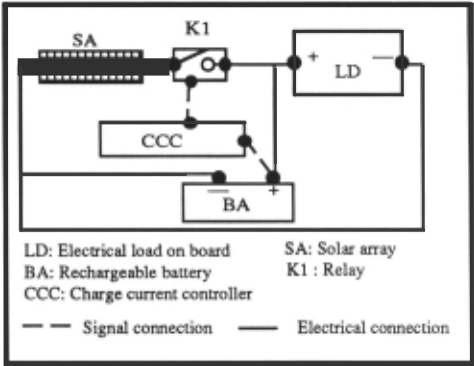
In this section, we give a brief overview of CFRL. CFRL is fully described in [Vescovi et al, 1993]. Before describing CFRL, we present the device that we will use throughout the paper as an example. The device is the electrical power system (EPS) aboard an Earth-orbiting satellite [Lockheed, 1984]. A simplified schematic diagram of the EPS is shown in Figure 2. The main purpose of the EPS is to supply a constant source of electricity to the satellite's other subsystems. The solar array generates electricity when the satellite is in the sun, supplying power to the load and recharging the battery. When the satellite is in a shadow, the battery supplies power to the load. Since the battery can be damaged when it is charged beyond its capacity, the charge current controller opens the relay when the voltage exceeds a threshold to prevent the battery from being over-charged.
CFRL allows one to explicitly state the physical context in which a function is to be achieved and to describe a function as an expected causal sequence of events. Since the concept of causal interactions among components is essential to the understanding of a function, the language allows explicit representation of causal interactions and constraints on such interactions. Figure 3 shows an example of the representation of an EPS function.
Formally, a function F is defined as a triplet {DF, CF, Gp}, where:
- D F denotes the device of which F is a function.
- C F denotes the context in which the device is to function.
- G F denotes a description of the functional goal to be achieved.
The notion of a device function assumes some physical context in which the device is placed, and C F is a specification of such a context. C F consists of two parts, a set of objects and a set of conditions on those objects. The conditions must hold throughout a behavior in order for the function to be satisfied by the behavior.
G F, the goal to be achieved by the function, is represented as a Boolean combination of Causal Process Descriptions (CPOs). Each CPD is an abstract description of expected behavior in terms of a causal sequence of events. The abstracted behavior is represented as a directed graph in which each node describes a state and each arc describes a temporal and (optionally) a causal relation between states.
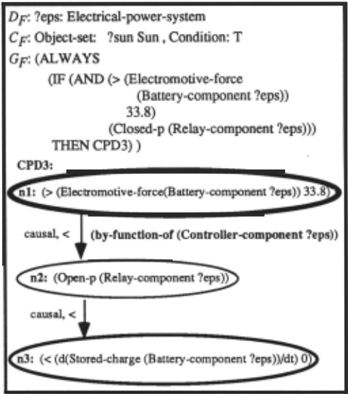
A node specifies a condition on a state. The condition is a logical sentence that must hold in a state of the world at some time using the variables defined in D F and C F. The arcs in a CPO are directed and specify temporal and causal relations among nodes. An arc has the following attrib~tes:
- causal-flag: An indicator of whether the relationship between the states described by the source and destination nodes is causal.
- temporal-relation: =, <, or ~, indicating the temporal relation between the states described by the source and destination nodes. = means that the states described by the two nodes are to be the same state, < means the state described by the source node must strictly precede the state described by the destination node, and ~ means the state described by the source node must either be the same as or precede the state described by the destination state.
- causal-justification: If an arc is "causal", one can attach a justification for the causal relation. A justification takes the form of a Boolean combination of the predicates by function-of (<component>) and with-participation-of (<component>). Those predicates are used to specify the participation of a device component in a particular portion of a causal process.
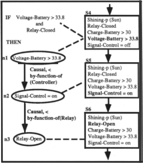
Because the semantics of CFRL is defined in terms of matching a functional specification to a device behavior, the language is immediately useful for design verification. In Figure 4, we show an example of matching a CPO to an EPS behavior generated by a qualitative simulator [Iwasaki and Low, 1991]. The left portion of Figure 4 shows part of an EPS function. (The notation has been changed slightly for legibility.) The right portion shows part of a predicted behavior for EPS. Since the IF part becomes true at state s4. s4 is matched against node nl. Nodes n2 and n3 match with s5 and s6. The temporal constraints on the arcs are clearly satisfied since s4 < s5 < s6. The way this portion of the behavior was simulated shows the existence of the following causal path involving the controller and the relay:
Voltage-battery> 33.8 [s41 ~ Tum-signal-on [s41 ~ Signal-control = on [ s5 1 ~ Relay-open [ s6 1.
Thus, as required by the arcs in the CPO, the functioning of the controller plays a role in causing the condition specified in node n2 to become true and the functioning of the relay plays a role in causing the condition specified in node n3 to become true.
3 A Design Support System
A comprehensive design support system needs to support multiple iterations through all the steps of design, including formulation, synthesis, analysis, evaluation, reformulation, and description, since any non-trivial design problem will require many such iterations. Furthermore, even though the requirements are the input in Gero's model, requirements are rarely completely known a priori. Even known requirements often change during the design process, a provision not allowed for in most formal models of the design process. During the process of generating and evaluating alternative designs, the designer may discover unforeseen consequences of given requirements or features of the environment that have effects on the performance. As a consequence, the requirements are likely to change many times. A practical design environment must support such incremental acquisition and evolution of the requirements. Our goal is to develop a design support system that can facilitate all these activities by:
- Providing languages for describing both device structure and functional specifications at various levels of abstraction.
- Supporting incremental acquisition of both constraints that must be satisfied by the device and properties of the environment in which the device is expected to operate.
- Providing analysis tools for evaluating the design through simulation and for verifying that the simulated behavior satisfies the functional specification.
We view the design process as one of parallel refinement of two types of specifications: physical and functional. The two specifications are closely linked in many ways. The functional specification drives development of the physical specification by providing the goals to be achieved. The functional specification refers to parts of the physical specification in order to explain how different components are to interact with each other to achieve the overall function. The physical specification must include at least all the components that are referenced in the functional specification and all connections that enable them to interact. Analysis of the behavior of the physical design in turn may suggest additional functions that are needed. Finally, the functional specification provides an important part of the rationale for the physical specification as well as the evaluation criteria for design.
The following section describes the design environment through a hypothetical design scenario.
3.1 Hypothetical Design Scenario
The given task is to design an electrical power supply (EPS) for an Earth orbiting satellite; The top-level goal is expressed in CFRL as shown in Figure 5.
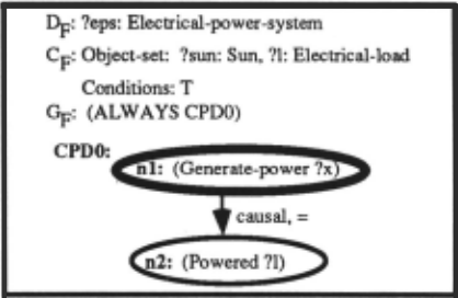
It says that the power supply generates power, supplying electricity to the load. The physical specification at this point, shown in Figure 6, is very simple. It shows that there is an electrical load connected to a power-supply.
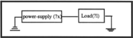
The designer first decides to refine the power-supply component in Figure 6 by selecting a specific class of devices as a power supply. The system, using its component library, displays the following options:
Power-supply options: battery, solar array, thermal generator
The user selects "battery". The physical specification is refined to include a battery as the power supply. The user wants to see the behavioral implications of this selection. The systems performs qualitative simulation of this abstract physical specification using its generic knowledge of batteries. The simulation results, as shown in Figure 7, indicate that the battery will run out of power at some unspecified time t, after which the load will not be supplied power.
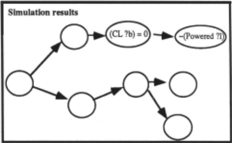
The system's verification module compares this predicted behavior with the top-level functional specification and informs the user that the function is not satisfied since the battery fails to supply power after some time. Furthermore, causal analysis by the verification module reveals that the failure to provide power causally depends on the capacity of the battery as well as the power demand by the load. These analysis results prompt the user to refine the functional specification by changing "ALWAYS" to "fort< 20 years" and by adding the constraint that the electrical load is 100 watts and constant.
The user now asks the system to describe types of batteries that can satisfy these constraints. The system, using its battery knowledge base, describes possible types of batteries that can meet these requirements and lists their attributes, such as the capacities they must have. One of the listed attributes is weight, which the system computes will be between 500 kg and 30,000 kg depending on the type of battery chosen. The user decides that this is unacceptable for use in a satellite. She adds a new constraint that the weight of the EPS must be less than 50 kg and rules out using a battery as the power supply.
The user now returns to the list of alternatives supplied by the system and selects a generator as the power supply. The component knowledge base contains knowledge about the a priori requirements of each type of componen~ for its operation. In the case of generators, the requrrements include the availability of some type of fuel such as oil, coal, gas, or uranium. Since the system does not know enough about the environment in which the EPS will operate to determine if any such fuel is available, the system displays this requirement, which leads the user to specify the environmental constraint that there is no fuel and to rule out use of a generator.
Similarly, the user considers solar arrays and is presented with the requirement that sun light be available. The user adds the environmental constraint that sun light is available only for 70 minutes out of every 100 minutes and rules out solar arrays.
Since none of the options for a power supply presented by the system fulfills the functional goal, the designer decides to combine batteries and solar arrays, so that the solar array can recharge the battery as well as provide power while the sun light is available, and the battery can provide power when sun light is not available. She modifies the functional and physical specifications accordingly. She further refines the physical specification by choosing a nickel-cadmium battery. These steps produce the specifications and constraints shown in Figure Sa and 8b.
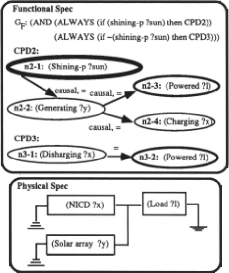
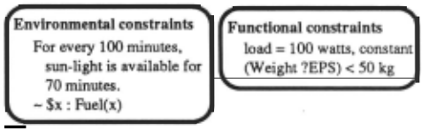
At this point, the designer decides to check the design by simulating its behavior. Predicted behavior indicates the possibility of the battery heating up and eventually becoming damaged. Noticing the battery heating up reminds the user that the scientific equipment on board the satellite should not be exposed to high temperature. She adds the functional constraint that the temperature of the EPS should not exceed 40° C. Causal analysis of the states in which the battery heats up and becomes damaged reveals that overcharging of the battery is the cause.
The designer modifies the design again to include a controller, whose behavior she specifies to be opening the connection between the solar array and the rest of the circuit when the battery becomes fully charged and closing it otherwise. This new design is shown in Figures 9a and 9b. It also shows the functional specification is refined to include the function of the controller. The lower part of the functional specification shows the behavior of the controller as specified by the designer.
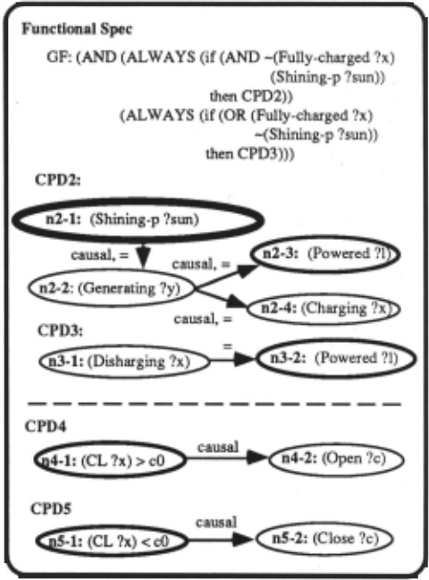
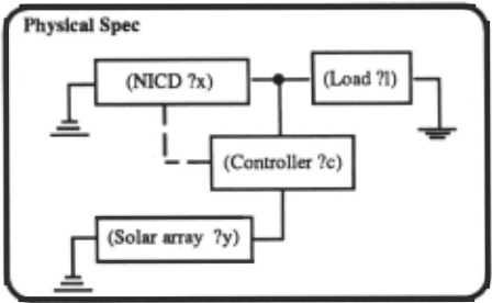
Simulating this new design reveals chattering behavior of the controller. The designer modifies the threshold for closing the controller in CPOS to c1 such that c1 < cO to eliminate chattering.
3.2 Summary
To summarize, the design support system described in this section has the following features:
- Allows specification at various levels of abstraction of the physical structure and the intended functionality of the device being designed. The functionality is represented using CFRL and describes what the device is to achieve and how.
- Aids analysis of the design by providing simulation facilities which can automatically formulate a simulation model of a given design and predict its behavior. At an early design stage, simulation can be performed qualitatively to uncover possible undesirable behaviors. The system also provides causal analysis of the undesirable behaviors to help refine the design.
- Aids evaluation of the design by a verification facility that compares a predicted behavior against the functional specification in CFRL to determine whether the predicted behavior achieves the desired function.
- Aids in selection of components by presenting alternatives and their characteristics, using its component library indexed by function.
- Allows incremental acquisition and refinement of various design requirements, including functional and environmental constraints.
The final products of a design process using this design environment include physical and functional specifications as well as a complete list of requirements and a description of the operating environment. The functional specification should include a detailed description of what the device is expected to do, how it is expected to do it, and under what circumstances. Furthermore, the history of the design process will be maintained in order to enable post-facto reconstruction of the design rationale.
4 Discussion and Conclusion
In this paper, we have described a design support environment which allows explicit representation and refinement of functional specifications along with physical specifications. CFRL is used to express the intended function of the device to be designed and how the function is to be achieved through causal interactions of its components. Knowledge of the intended function of the device allows the system to evaluate the design of the physical structure during the design process to provide useful feedback to the designer even at an early stage of the design.
The described design support system is being implemented as an extension of the existing DME system. DME already contains model formulation and simulation facilities, a device structure editor, and an explanation facility [Gruber and Gautier, 1993]. An efficient algorithm for automatically formulating an appropriate simulation model for a given query has been developed and implemented [Iwasaki and Levy, 1993]. We have also implemented a behavior verification program based on CFRL [Vescovi et al, 1993].
As Gero points out, designing the expected behavior, i.e., what the device is to achieve and how, is an important part of the entire design process. Furthermore, in practical design problems, the requirements are not fully known initially but they are modified, augmented, and refined during the design process partly in response to analysis results of the design being developed. Therefore, a design environment must support such incremental acquisition of requirements as well as functional specifications.
A design support system needs to maintain a history of the design process, including development of the functional and physical specification, acquisition of requirements, and analysis performed of intermediate designs, including the desirable or undesirable behaviors discovered which led to further refinement of the design. Such a record can be used later to reconstruct not only rationale for the design of the physical structure, but also rationale for requirements and functional specifications.
There has been significant previous work on both representation of function and its use in reasoning about physical devices. CFRL is based on the work on Functional Representation [Sembugamoorthy and Chandrasekaran, 1986], and it is a further extension of the work presented in [Iwasaki and Chandrasekaran, 1992]. We have extended the expressive power of the language described in those papers, and have provided a formal foundation of the semantics of the language to make possible its use for verification of design. Franke [1991], and Bradshaw and Young [1991] also represent the intended function in a manner similar to Functional Representation. An important characteristic that distinguishes CFRL from the work of Franke, Bradshaw, and Young is the role causal knowledge plays in CFRL and its use in verification. Our work is based on the conjecture that causal relations are an essential part of functional knowledge, and that explicit representation and verification of such relations is important in ascertaining that the design achieves the intended goal.
Lee and Lai [1991] make a useful distinction between two types of design rationale: (1) a record of the exploratory activity of the design team, and (2) an account of how the designed artifact satisfies expected functionalities. The design support system described in this paper captures the latter type of rationale. It is a step towards realizing the view of functional representation as design rationale discussed by Chandrasekaran et al [1993]. As such, the system we have described concentrates mostly on acquiring infonnation about the structural and behavioral aspects of the device to be designed, but does not handle the full range of possible types of design rationale. There has been much work on development of systems for design rationale capture [Klein, 1993; Fischer et al, 1991]. In contrast to our work, most of them concentrate on capturing the second type of rationale in the fonn of argumentation structure (pros and cons) for individual features of the design. Few offer a representation fonnalism expressive enough to capture detailed functional knowledge of how the design is intended to achieve its goal, nor do they treat the development of the functional specification as a distinct activity in the design process. We believe that a comprehensive design support system must be able to represent and reason about both types of infonnation, and we intend to extend our system to handle the full range of infonnation involved in device design.
Acknowledgements
We would like to thank Steven Cousins, William Fung, Hiang-Kwee Ho and James Rice for their contributions to the discussions during which the extensions to DME described in this paper were refined.
@inproceedings{ijcai1993p210,
  title     = {How Things are Intended to Work: Capturing Functional Knowledge in Device Design},
  author    = {Iwasaki, Yumi and Fikes, Richard and Vescovi, Marcos and Chandrasekaran, B.},
  booktitle = {Proceedings of the Thirteenth International Joint Conference on
               Artificial Intelligence, {IJCAI-93}},
  publisher = {International Joint Conferences on Artificial Intelligence},
  editor    = {Ruzena Bajcsy},
  pages     = {1516--1521},
  year      = {1993},
  note      = {Qualitative Reasoning and Naive Physics},
  url       = {https://ijcai.org/proceedings/1993/210},
}
TY - CPAPER TI - How Things are Intended to Work: Capturing Functional Knowledge in Device Design AU - Iwasaki, Yumi AU - Fikes, Richard AU - Vescovi, Marcos AU - Chandrasekaran, B. T2 - Proceedings of the Thirteenth International Joint Conference on Artificial Intelligence, IJCAI-93 PB - International Joint Conferences on Artificial Intelligence PY - 1993 SP - 1516 EP - 1521 UR - https://ijcai.org/proceedings/1993/210 ER -Copied
Machine-readable versions of this paper, for tools and AI agents:





