
Using Line Correspondence Stereo to Measure Surface Orientation
Proceedings of the Eleventh International Joint Conference on Artificial Intelligence. Vision and Robotics. Pages 1655-1659.
© 1989 International Joint Conferences on Artificial Intelligence
Abstract
Accuracy of geometric measurement of object environments for robotic vision tasks is of increasing importance as these tasks become more sophisticated. This paper is concerned with the accurate measurement of orientations of lines and planar surfaces from two camera stereo. Most existing stereo algorithms build up geometric descriptions from absolute position information about points. We emphasize in this paper the accuracy advantages of determining orientation of lines and planar surfaces using the correspondence of linear features instead of point features. Intuitively, the determination of only orientation from absolute position measurement of points uses too much information which requires the unnecessary accurate calibration of certain camera parameters. Orientation information is invariant to knowledge about absolute positional information . If the orientation of lines are computed from the intersection of planar sheets of projection from a stereo pair of cameras, in the absence of all camera errors, the result is independent of baseline. Orientation of planar surfaces can be determined from the cross product of the orientations of at least two coplanar linear features. It is shown that even in the presence of typical camera errors ·that measurement of the orientations of lines and surfaces using line correspondence stereo is relatively insensitive to baseline errors. Even more, the measurement of orientation from line correspondence stereo is relatively insensitive to typical localization error on the image plane. As a result orientations of lines and planar surfaces far from the baseline can be measured much better using line correspondence stereo rather than point correspondence stereo.
- Bajcsy et al. 1987]
- Bajcsy, R., Krotkov, E., and Mintz, M., Models of errors and mistakes in machine percep- tion, Proceedings of DARPA image understanding workshop, pp.194-204,1987.
- Duda and Hart 1973]
- Duda, R ., and Hart, P., Pattern Classification and Scene Analysis, New York, 1973.
- Matthies and Shafer 1987]
- Matthies, L., and Shafer, S.A., Error modeling in stereo navigation, IEEE Journal of Robotics and Automation, Vol. RA-3, No. 3, June 1987.
- McVey and Lee 1982]
- McVey, E.S. and Lee, J.W., Some accuracy and resolution aspects of computer vision distance measm•ements, vol. PAMI-4, pp. 646-649, 1982 .
- Milenkovic and Kanade 1985]
- Milenkovic, V.J., and Kanade, T ., Trinocular vision using photomet1•ic and edge orientation constraints, DARPA image understanding work- shop, 1985, pp.163-175.
- Photogrammetry 1966] Manual of Photogrammetry, Amer. Soc. of Photogrammetry, 1966 .
- Solina 1985
- Solina, F ., Errors in stereo due to quantiza- tion, Univ. Pennsylvania, Tech. Rep. MS-CIS-85-34, Sept. 1985.
- Torre et al. 1985]
- Torre, V., Verri, A., and Fiumicelli, A., Stereo accuracy for robotics, International Symposium of Robotics Research , pp.5-9, 1985.
- Verri and Torre 1986]
- Verri, A. and Torre, V., Absolute depth estimates in stereopsis, J. Opt. Soc. Amer., vol. 3, no. 3, pp.297-299, March 1986.
References were extracted automatically from the PDF and may contain errors.
Full text extracted automatically from the PDF; figures, tables and equations may differ. The PDF is the version of record.
1 Introduction
Point correspondence stereo determines the absolute position of points in space, and from these points builds up geometric descriptions of objects. Line correspondence stereo deter mines the orientation of lines in space without necessarily knowing the absolute position of these lines. In the ideal world, with zero measurement error, the geometric construc tions of planes from points and lines are exactly equivalent.
*This work was supported in part by ARPA grant #N00039-84-C0165 and NSF grant IRI-88-00370. This work was supported in part by an IBM Graduate Fellowship Award.
Terrance E. Boult Computer Science Department Columbia University New York, N.Y. 10027
So then why bother to analyze another stereo algorithm using equivalent geometric constructions ? The fact is, these geo metric constructions are equivalent only in the ideal world. In the real errorful world, where accuracy of measurement is at a premium, orientation measurement of lines and planar surfaces from line correspondence stereo show certain signifi cant superior accuracy properties. Among the advantages of line correspondence stereo over point correspondence stereo, with respect to orientation measurement, are relative insen sitivity to baseline errors, and slower error growth rate as the distance from the object to the baseline increases. These advantages will be demonstrated through simulation.
Accurate measurement of surface orientation is important to a variety of robotic vision tasks. Accurately determining the orientation of a block can enable a robot manipulator to more dexterously grasp the block. For mobile robots, accu rate orientation information about objects enables navigation parallel to these objects and better obstacle avoidance. Ac curate orientation measurement of a surface may in turn be used to increase the accuracy of absolute measurements of points that lie on the surface, originally obtained from stereo using absolute correspondence of points. The stereo method presented in this paper obtains orientation information inde pendent of depth information about individual points. If sur face orientation can be measured more accurately from this new stereo method, then points whose absolute location has been determined from conventional stereo can be projected onto a plane whose orientation is more consistent with that of the physical surface. The plane would be oriented accord ing to the orientation measurement from the former stereo method and positioned according to a least squares fit to the points obtained from the latter stereo method. Analysis of how these two stereo methods complement one another to wards the accurate determination of absolute point location
is saved for future research.
Lines in space are determined by line correspondence stereo from the intersection of planar sheets of projection generated from the focal point and the imaged line from each camera. Surface orientation can be computed from the cross product of orientations for linear features that are known to lie on the surface (e.g., two edges of a polygonal surface). Surface orientation can also be computed from virtual lines which may in fact not exist as true physical linear features but which are imaginary lines that connect corresponded physi cal point features on a planar object surface. As for the measurement of the orientation of the lines themselves, what is of importance is not whether the intersecting planar sheets produce the exact line in space, but whether the line that is produced is parallel to a high degree of accuracy to the orig inal line. This is different from the usual utilization of stereo towards triangulating the absolute location of the feature.
Because the orientation of lines are invariant with respect to their translation in 3-D space, the computation of orienta tion from the intersection of planar sheets can be performed without any knowledge whatsoever of the baseline between the stereo pair of images.
After discussion of how to compute line and planar surface orientation from line correspondence stereo, we delve into an error analysis comparing line orientation measurement errors produced from line and point correspondence stereo. The er ror analysis for point correspondence stereo is largely based upon the articles by [Verri and Torre 1986] and [Torre et al. 1985], which discuss the dependency of absolute measurement error of points upon translational baseline errors and local ization error in the image plane. Different aspects of errors in point stereo measurement are also analyzed in [Bajcsy et al. 1987], [Matthies and Shafer 1987], [Salina 1985], [Mcvey and Lee 1982], and [Photogrammetry 1966].
The main error that effects the computation of line orien tation from intersecting planes is in the determination of the slope of the imaged lines in the image plane. A large number of computer simulations were performed to assess how big a slope error is acceptable to outperform stereo techniques us ing absolute point correspondence to determine the orienta tion of surfaces. Following the survey of commonly used CCD cameras presented in [Torre et al. 1985], pixels are assumed to be 20 microns square. Localization of corresponding point features is assumed to be within two pixels. The focal length used is assumed to be 1 em which is consistent with the analy sis presented in [Verri and Torre 1986] and [Torre et al. 1985]. This focal length is typical for cameras mounted on a mobile robot or for a robot workstation to attain wide enough field of view. A two pixel localization error for imaged lines was simulated, but this had trivial effect upon the method using intersecting planes since two pixels is a very small distance compared to the focal length.
It should be noted that the method of intersecting projected planar sheets from imaged lines was used in (Milenkovic and Kanade 1985] for the purpose of providing constraints for line matching in trinocular stereo. The pre sentation below is the first to suggest that the projection of planar sheets from stereo pairs of imaged lines can be used to accurately measure line and surface orientation.
2 Determining Line and Surface Orientation From Line Correspondence Stereo
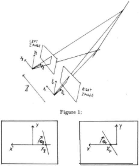
One geometric definition of a line is that it is determined by the intersection of two planes. Thus a line can be determined in space from a stereo pair of images as depicted in figure 1 by the projection of planar sheets determined by the focal point and the imaged line in the image plane. One advantage of this geometric construction of a line is that the orientation of the line is completely invariant with respect to how the planar sheets of projection are translated in space with respect to one another.
The proof of this invariance is simple. The orientation of a line determined by two intersecting planes can be com puted from the cross-product of the normals to the intersect ing planes. This is because the line of intersection is per pendicular to both normals, since it must lie simultaneously in both planes. The normals to both intersecting planes are clearly invariant to arbitrary translation.
The computation of the orientation of a line formed from two planar sheets of projection is formed from the cross product of the normals to the two planar sheets. The normal for each planar sheet of projection is in turn computed from the cross-product of the vector from the focal point to a point on the line in the image plane, with the vector representing the orientation of the line in the image plane. Let (xr ,Yr) and (xz, yz) represent points on the imaged line in the im age plane of the right and left images respectively. These points need not correspond at all. All that is required is that the imaged lines correspond in both images. The angle that each imaged line makes with the positive x-axis in the image plane is Br and 81 for the right and left images respectively. These parameters are depicted in figure 2. Assume that the focal length for both cameras is f. The normal to the pla nar sheet of projection generated from the right camera in the right camera coordinate system is formed from the cross product of the vector going from the focal point, (0, 0, 0), to the image point, (xr, Yr, !), with a vector parallel to the im aged line (e.g., (cos8r, sin8r, 0)). The normal to the planar sheet generated from the left camera in the left coordinate system is produced from the analagous vector product. In actual implementation, the vector parallel to the imaged line was computed from the vector difference of two points on the imaged line. Ultimately, the vector cross product of the normals to the planar sheets will be expressed in the right camera coordinate system, so that the normal to the pla nar sheet of projection generated from the left camera must be rotationally transformed into the right camera coordinate system. If the image planes are pure translations with respect to one another then no rotational transformation is required. If however the lateral inward vergence in the x - z plane is assumed to be /3, then the rotational transformation of coor dinates from the left camera coordinate system to the right camera coordinate system is given by the rotation matrix:
In actual implementation, this rotation is more complicated involving all three Euler rotation angles.
Finally, the 3-dimensional vector orientation of the line formed from the intersection of the two planar sheets of pro jection is parallel to the following vector in the coordinate system for the right image:
If the x-intercept is used for the point on the imaged line both images, then Yr = Yl = 0 and the above expression 1n Slm plifies to
(
This vector can be normalized to unit length. Clearly the expression for the orientation of the line is independent of the baseline vector l.
This stereo method using projected planar sheets can be used to determine surface orientation. Using equation 1 de termine the orientation vectors of two linear features lying on the same surface. Taking the cross product of these two vectors yields a measurement of the surface orientation. In the absence of camera errors other than translational error, surface orientation error is independent of any baseline errors.
3 Error Analysis For Measured Line Orientations
Unlike the derivation of points from intersecting projected rays for point correspondence stereo, the derivation of a line using intersecting planar sheets is very insensitive to local ization error. This is due to the fact that this error is usually very small compared to the focal length of the camera lens (e.g., the localization error of a 20 micron pixel is 1/500 of a 1 em focal length). Thus the orientation deflection error of each projected planar sheet due to typical localization errors for a line is very small. This fact makes determination of line and surface orientation from line correspondence far superior to equivalent determinations from stereo point correspondence, at distances far from the baseline.
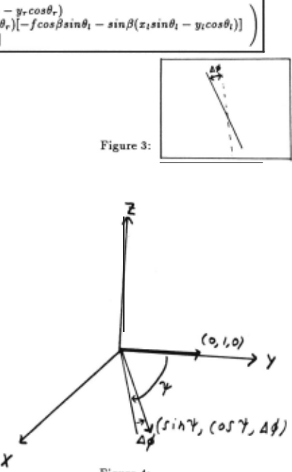
Line correspondence stereo. is most sensitive to errors in herent to the slope of imaged lines used in line correspondence pairs. Consider the measurement orientation error incurred on a vertical line determined from the intersection of two pro jected planar sheets, when one of the planar sheets is deter mined from an imaged line with slope error tlt/J. The imaged line slope error is depicted in figure 3. The incurred error on one of the normals to a projected planar sheet is depicted in figure 4. The worst case incurred error on the orientation of the line in space resulting from the intersection of the two projected planar sheets is the angle between the following cross product vectors:
The worst case orientation error of the line in space is there fore tan- 1 (tlt/J/sin,P) where '1/J is the angle between the error free normals of .the two intersecting planar sheets. Clearly, for given image slope error, the deflection of the line in space is largest when the intersecting planes are almost parallel (i.e., when '1/J ~ 0). Consider now adding to the inherent image slope error tlt/1, a worst case baseline translation error tlx for each camera, parallel to the baseline. Assuming the error free baseline length to be l, and the perpendicular distance of the vertical line to be z from the midpoint of the baseline, the worst case orientation error, Berror, is given by:
The increase in worst case orientation error as z is increased is due to the fact that the vertical line 1 is derived from intersecting projected planar sheets that are more parallel. That is, '1/J decreases as z increases.
An analysis of depth estimation errors for point stereo is given in [Verre and Torre 1986]. Assuming imaged point lo calization error of tlq in both cameras, and baseline transla tion error tlx parallel to the baseline,
where f is the focal length. Suppose now that the determi nation of the orientation for a line is constructed from two
1 The measurement of a vertical line is used because it exhibits a worse case deflection with respect to given image line slope error !:;.~ . The equivalent of equation 2 for when imaged line slope error t:;.~ is used for both cameras is far more complicated but exhibits the same basic algebraic properties with respect to dependence on t:;.~ and z.
points at distance mo apart. From point stereo, using there sults of [Verre and Torre 1986], the orientation error, Berror, of the line is given by:
where k1 and k2 are constants.
Comparing equations 2 and 3, the advantages of using line correspondence stereo over point stereo for determination of line orientation becomes clear. As a function of z, the per pendicular distance to the baseline, equation 3 is dominant in tan- 1 (z 2 ) while equation 2 is dominant in tan- 1 (z). Thus for line correspondence stereo, orientation error for lines should grow significantly less rapidly than for point stereo as the dis tance between the baseline and the line increases. Consider the invariance of equation 2 and 3 with respect to baseline translational error, 6x. Typically 6x is some fraction of l, so an increase of 6x, say, from 10% of l to 20% of l has rela tively little effect on equation 2. However, the fact that 6x has doubled, in this example, has a significant effect on equa tion 3, especially for large z. Thus, line correspondence stereo is much less sensitive to baseline translation error, than for point stereo. Also, looking again at equation 2, in the limit as 61/J goes to 0, Berror becomes very small. This means that the more accurately one is able to measure the slope of im aged lines, the less significant becomes baseline translation error and the distance z from the baseline.
We have done some elementary analysis on the comparison of orientation errors of lines determined from line correspon dence stereo and point stereo. For comparison of orientation errors for surfaces, simulating more physical errors other than localization, slope and baseline translation errors, the equa tions become vastly more complicated. In the next section, we resort to Monte Carlo simulation, using typical physical parameters. As will be seen, as compared to the determina tion of surface orientation from point stereo, line correspon dence stereo is less sensitive to baseline translation error and distance z from the baseline.
4 Monte Carlo Simulations for Determination of Surface Orientation
This section will analyze the accuracy of the measurement of surface orientation from the stereo method of intersect ing projected planes from line correspondence. This will be compared with the accuracy of the stereo method of absolute correspondence of points which is used to determine the abso lute position of three points that lie on the same surface and then the plane going through them. In practice more than three points may be used with a least squares planar fit, and so can multiple linear features on the same surface be used by the stereo method using planar sheets. To attain a more di rect comparison of these two stereo methods with respect to the accuracy of determining surface orientation, simulations will be conducted using two linear features for the method using planes of projection and three point features for the method using rays of projection. The stereo method using intersecting planes uses equation 1 and the stereo method using absolute correspondence of points uses the standard method proposed in [Duda and Hart 1973] whereby points of intersection for nonintersecting rays are determined at the point of closest approach.
As mentioned in the introduction, a focal length of 1 em with a pixel size of 20 microns square (0.002 of a focal length) will be assumed. Actual data will be presented simulating a triangular object about 15 em on each edge with surface ori entation about 14 degrees from the optic axis of both cameras whose image planes are assumed parallel. This simulation data is representative of many other simulations that were performed with the triangular object in various orientations at various locations and for triangular objects twice as large. Using different angles of vergence up to 30 degrees between the two cameras did not appear to make that much difference in computing the accuracy of surface orientation. Errors in all rotational degrees of freedom of the image planes were simulated at ±0.5°. Localization error for points and lines is ±2 pixel lengths. For a given 3-dimensional translation error, c, for a camera, the optic center is assumed to lie with equal probability at all points within a cube centered about the assumed position of the optic center, with each side being c. For a given baseline, with given translation error in the optic center and given slope error in the image plane, worst case and average case errors were derived for orientation of the triangular surface from 1000 simulations.
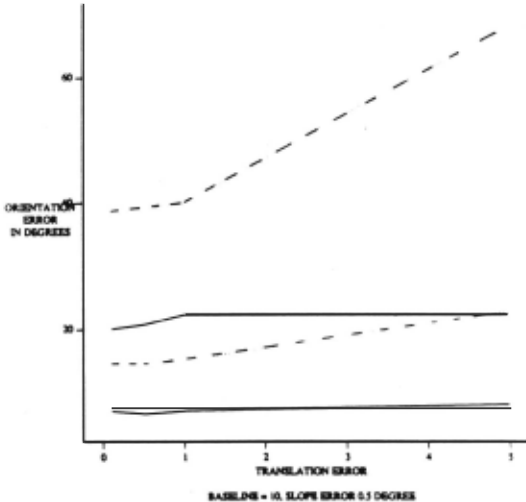
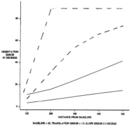
Figures 5 and 6 show simulations using a 10 em baseline for different imaged line slope errors of 0.5 and 1.0 degrees. The object is placed 1 meter from the baseline. The solid lines represent the average case and worst case performance of the stereo method determining surface orientation using in tersecting planes. It should be clear that the upper solid line graph is for the worst case error. The dashed lines represent graphs for the average case and worst case performance of the stereo method using absolute correspondence of the cor ner points. All solid and dashed lined graphs in other figures have similar meaning. The translation errors on the hori zontal axis represent the bounds in translational uncertainty in all 3 degrees of translational freedom. So for instance a translation error of 1 on the horizontal axis implies that the uncertainty is equal probability within the cube formed from ±1 em of the assumed position of the camera.
Observe the stability of the measured orientation error for the stereo method using intersecting planes as the transla tional error gets larger. The average and worst case errors represented by solid lines stay relatively flat through rather large translation errors. Hence the approximate translational invariance of the stereo method using intersecting planes in the presence of other camera errors. This is not true for the average and worst case errors represented by dashed lines. The measured orientation error climbs significantly for the stereo method using absolute correspondence of points past a translation error of approximately 5% of the baseline. For a slope error of 0.5 degrees for the stereo method using in tersecting planes, the relative performance compared to the stereo method using absolute correspondence of points is at least 50% for small translational errors, and gets much better as translation error grows. Using a 100 em baseline, it can be seen in figure 6a that this relative performance is better than 10 to 1 for a translational error of ±20 em.
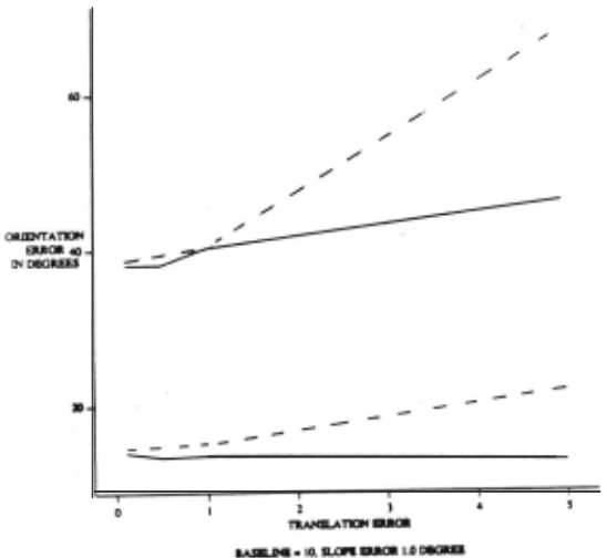
Figure 7 shows error curves using a baseline of 20 em, a slope error of 0.5 degree for stereo using intersecting planes, and a relatively small translation error of ±1 em. As a func tion of object distance from the baseline, orientation error from stereo using intersecting planes is far more stable than for orientation error measured from stereo using absolute cor respondence of points.
Note that the worst case of orientation error is at 90°. Due to rotation errors in the image plane and quantization error, the worst case error for orientation error for the stereo method using the absolute correspondence of points is at 90° throughout most of figure 7. At first this may look wrong but the uncertainty in the absolute z-depth just due to the quan tization (localization) error alone goes up as the square of the distance of the object from the baseline. The exact same pixel size and focal length used here is used in the analysis in [Veni and Torre 1986). Extracting from their analysis , for a baseline of 20 em and an object distance of 2 meters, the worst case error in the absolute z-depth of each corner point is 4 em. Compare this to the size of an object with 15 em edges and add on errors in absolute position measurement from orientation errors in the rotation of the image plane of ±0.5°. It is clear that the measurement of surface orienta tion from the stereo method using intersecting planes is very compelling in this case.
5 Limitations and Future Work
One of the problems we have conveniently ignored, is the dif ficult problem of stereo matching. This problem is inherently difficulty, even with the stringent assumptions that are made by many traditional stereo matching system. If we are to realize the full benefit of this new algorithm, the matching problem becomes even more difficult because we are assuming less accurate knowledge about the relative orientations of the imaging system. Thus we must relax the epipolar assump tions to allow for much larger errors in the exact position of the cameras. In addition, for matching lines, one generally wants to allow a segment to have multiple matches provided the matches to do not spatially overlap.
In addition, we have a secondary matching problem: to compute surface normals requires matching pairs of lines be tween the two images. Thus, we not only need to match lines from the images, we must be able to identify two matched sets which come from the same planar patch of the world. There are a number of heuristics that come to mind for this problem, but there is little past work to build upon.
Luckily, the method not only brings problems for the stereo matching phase, it also has the potential to help in match ing. Future research will address fusing orientation and point based information to determine if we may get both increased accuracy in the matching and increased accuracy in the ori entation computations.
Another limitation of the approach, as presented, is that it assumes lines with reasonably accurate slope information. Unfortunately, getting such information from real images is nontrivial, and for some scenes there are no long linear fea tures. An area for future work, which will help alleviate these problems, is the idea of determine orientation from the slope changes of virtual lines. Given any pair of stable, matchable features in a pair of images, we can use these to define a line with a known slope. These virtual lines should allow a sig nificant increase in the amount of information (with many features, the numbers of possible pairs grows greatly), bet ter feature localization, and extending the domain to scenes where long linear features are not present.
A new stereo method was presented for the measurement of the orientation of surfaces from at least two linear features lying on the surface (e.g. surface edges). This uses the projec tion of planar sheets each determined by the focal point and a corresponded image line from each camera. Simulations were presented which compared the accuracy of the measurement of surface orientation from this new stereo method relative to this measurement from stereo which uses the absolute cor respondence of points.
It was shown that there are two major advantages to us ing this new stereo method using intersecting planes. First, once two coplanar linear features in space are imaged by a stereo pair of cameras, the orientation measurement error is relatively independent of the baseline, even in the presence of realistic errors in other camera parameters. Second, ori entation error does not grow quickly as a function of how far the object is away from the baseline. This is particularly a big advantage over stereo using absolute correspondence of points.
A possible disadvantage of stereo using intersecting planes is the accuracy to which the slope of lines may need to be determined in the image plane. For common objects at 1 me ter from the baseline a slope accuracy of ±0 .5° performs very well. This might be too stringent for shorter line elements. However, accuracy of slope error quickly relaxes as the object moves away from the baseline. It appears for most objects beyond 2 meters from the baseline, having edge lengths com parable to those that were simulated, that at least a ±2 de grees slope error could be tolerated with the accuracy perfor mance of stereo using intersecting planes being much better than for stereo using absolute correspondence of points. This issue will be further explored in future experimentation.
@inproceedings{ijcai1989p263,
  title     = {Using Line Correspondence Stereo to Measure Surface Orientation},
  author    = {Wolff, Lawrence B. and Boult, Terrance E.},
  booktitle = {Proceedings of the Eleventh International Joint Conference on
               Artificial Intelligence, {IJCAI-89}},
  publisher = {International Joint Conferences on Artificial Intelligence},
  editor    = {N. S. Sridharan},
  pages     = {1655--1659},
  year      = {1989},
  month     = {8},
  note      = {Vision and Robotics},
  url       = {https://ijcai.org/proceedings/1989/263},
}
TY - CPAPER TI - Using Line Correspondence Stereo to Measure Surface Orientation AU - Wolff, Lawrence B. AU - Boult, Terrance E. T2 - Proceedings of the Eleventh International Joint Conference on Artificial Intelligence, IJCAI-89 PB - International Joint Conferences on Artificial Intelligence PY - 1989 SP - 1655 EP - 1659 UR - https://ijcai.org/proceedings/1989/263 ER -Copied
Machine-readable versions of this paper, for tools and AI agents:





