
Three-Dimensional Interpretation of Quadrilaterals
Proceedings of the Eleventh International Joint Conference on Artificial Intelligence. Vision and Robotics. Pages 1610-1615.
© 1989 International Joint Conferences on Artificial Intelligence
Abstract
Quadrilaterals are figures with which everybody becomes familiar in his/her very early stage of education. By studying these seemingly simple figures we can obtain some insights into the nature of the general problem of interpreting image contours. This paper discusses in detail how quadrilaterals are interpreted three-dimensionally, and draws feasible inferences about the general properties of the human system of processing line drawings. First the rectangularity regularity is proposed to be the prime constraint in the visual interpretation of quadrilaterals. The subjective "image center" and focal length (finite and infinite) are determined together with rectangle orientation. Secondly, interpretation of quadrilaterals as faces of a rectangular polyhedron is examined at both the geometrical level and the perceptual level. Finally the gravity regularity is proposed to derive constraints on the rectangle orientation by analyzing the relation among the camera, the ground and the rectangles supported by the ground.
- Barnard, S. (1983) Interpreting perspective images, Artificial Intelligence 21, pp. 435-462
- Barnard, S. and Pentland, A. (1983) Three dimen- sional shape from line drawings, Proc. 8th Int. Joint Conf. on Artificial Intelligence, pp. 1061-1063 IJCAI
- Barrow, H. and Tenenbaum, J. (1981) Interpreting line drawings as three-dimensional surfaces, Artificial In- telligence 17, pp. 75-116
- Brady, M. and Yuille, A. (1984) An extremum prin- ciple for shape from contour, IEEE Trans. on Pattern Analysis and Machine Intelligence, Vol. 6, pp. 288-301 1616 Vision and Robotics IJCAI
- Hoffman, D. and Richards, W. (1986) Parts of recog- nition, From Pixels to Predicates, ed. by Pentland, A., Ablex Huffman, D. (1971) Impossible objects as nonsense sentences, Machine Intelligence 6, ed.
- by Meltzer, B. and Michie, D., Edinburgh University Press
- Kanade, T. and Kender, J. (1983) Mapping image properties into shape constraints: Skewed symmetry, affine-transformable patterns, and the shape-from-texture paradigm, Human and Machine Vision, ed. by Beck, Hope and Rosenfeld, Academic Press Kanatani, K . (1986) The constraints on images of rect- angular Polyhedra, IEEE Trans. Pattern Analysis and Machine Intelligence, Vol. 8, pp. 456-463
- Kanizsa, G. (1979) Organization in Vision: Es- says on Gestalt Perception, Praeger Mackworth, A. (1973) Interpreting pictures of poly- hedral scenes, Artificial Intelligence 4, pp.121-137
- Palmer, S. (1983) The psycology of perceptual organi- zation: A transformational approach, Human and Ma- chine Vision, ed. by Beck, Hope and Resonfeld, Aca- demic Press
- Pentland,A. (1986) Introduction: From Pixels to Pred- icates, From Pixels to Predicates, ed. by Pentland, A., Ablex Perkins, D. (1983) Why the human perceiver is a bad machine, Human and Machine Vision, ed. by Beck, Hope and Resonfeld, Academic Press Reuman, S. and Hoffman, D. (1986) Regularities of nature: The interpretation of visual motion, From Pixels to Predicates, ed. by Pentland, A., Ablex Sedgwick, H. (1987) Layout2: A production system modeling visual perpspective information, Proc. 1st Int. Conf. on Computer Vision, pp. 662-666
- Stevens, K. (1981) The visual interpretation of surface contours, Artificial Intelligence 17, pp. 47-73
- Stevens,K. (1986) Inferring shape from contours across surfaces, From Pixels to Predicates, ed. by Pentland, A. , Ablex Struik, D. (1961) Differential Geometry, Addison- Wesley Sugihara, K. (1986) Machine Interpretation of Line Drawings, MIT Press
- Tsuji , S., Zheng, J . and Asada, M. (1987) Stereo vision of a mobile robot: World constraints for image matching and interpretation, Proc. IEEE Int. Conf. Robotics and Automation, pp. 1194-1199
- Turner, K . (1974) Computer perception of curved ob- jects using a television camera, Ph.D. Dissertation, Ed- inburgh University Ullman, (1979a) The Interpretation of Visual Motion, MIT Press
- Ullman, (1979b) The Interpretation of structure from motion, Proc. of the Royal Society, London, B203, pp. 405-426
- Xu, G. and Tsuji, S. (1987a) Inferring surfaces from boundaries, Proc. 1st Int. Conf. on Computer Vi- sion, pp. 716-720
- Xu, G. and Tsuji , S. (1987b) Recovering surface shape from boundary, Proc. lOth Int. Joint Conf. on Arti- ficial Intelligence, pp. 731-733 IJCAI
References were extracted automatically from the PDF and may contain errors.
Full text extracted automatically from the PDF; figures, tables and equations may differ. The PDF is the version of record.
1. Introduction
An image is a two-dimensional projection of a three dimensional scene, and a contour image represents signifi cant changes in surface shape, reflectance and illumination, which are reflected directly or indirectly in the 2-D image. A contour image can be a line drawing, drawn by human hands, which only includes topologically well-defined, se mantically significant, but not necessarily positionally ac curate contours; or it can be generated by computer from a real image, which may include many noise edges, if not processed very carefully.
Line drawing is probably the most abstract and ef ficient means of describing our 3-dimensional world in a 2-dimensional manner. Thus it is often used in human communications and is potentially very useful in human machine interfaces. Although the contours alone do not provide sufficient constraints on the surfaces, humans seem not to have any difficulty in recovering 3-D shapes from the 2-D contours. The task is so effortless for our eyes that we rarely pause to ask ourselves how we do. As we try to answer, however, we realize that it is a difficult question.
t The work was done at Osaka University. Dr. Gang Xu's address from this autumn is Center of Information Science, Peking University, Beijing, China
A number of papers have been published that try to answer this "shape from contour" question. Among them are [Barrow & Tenenbaum, 1981], [Kanade, 1981] , [Barnard, 1983] and [Brady & Yuille, 1984]. All the pa pers listed above generally deal with only closed contours and assume that the image contours are, globally or lo cally, projections of planar space curves. Ellipses are inter preted as circles by additional assumptions of: uniformity of curvature [Barrow & Tenenbaum, 1981], maximum en tropy [Barnard, 1983] and maximum compactness [Brady & Yuille, 1984], and quadrilaterals or parallelograms are in terpreted as rectangles by additional assumptions of maxi mum symmetry [Kanade, 1981; Barnard, 1983]. Reviewing the papers, it is not difficult to find that the approaches are based on the psycological facts that ellipses and quadri laterals (including parallellograms) are perceived as circles and rectangles, respectively. The approaches differ only in how the facts are accounted for and in what specific criteria they choose to achieve the predetermined aims. The psycology of line drawing perception was first studied by the Gestalt school. They propose priignanz, or figural goodness, to be the criterion on which the human per ception is based. The circle and rectangle interpretations are preferred because they are the most beautiful inter pretations among the possible. Unfortunately, however, the Gestalt psycologists could not give a theoretical ac count of the term priignanz from a standpoint of informa tiol_l processing, and figural goodness remains to be judged mrunly by human eyes (note that a recent progress is an at tempt to characterize pragnanz by transformational invari ance [Palmer, 1983].) The lack of a definition of priignanz leaves room for proposal of various specific criteria. The uniformity of curvature, entropy, compactness and symme try criteria are developed in, and thus well suited to the specific cases, but they are not surely universal and may not apply to other cases.
Under the circumstances, two general paradigms are available. The first is the quantitative paradigm, in which a universal criterion is developed and interpretations are selected by maximizing or minimizing that criterion as done in [Barrow & Tenenbaum, 1981], [Barnard, 1983] and [Brady & Yuille, 1984]. The second is the qualita tive paradigm, in which specific figural configurations that have definite interpretations are searched for and inter preted. Examples are [Stevens, 1981&1986], in which par allel (curved) contours are interpreted as lines of curva ture on a cylindrical surface, [Xu & Tsuji, 1987a,b], in which a closed boundary is segmented and interpreted as four lines of curvature if certain conditions are satisfied, and [Barnard & Pentland, 1983], in which elliptic arcs are directly interpreted as circular arcs. The causal relation between the interpreted and the interpretation is referred to as regularity. The task is thus to discover regularities, or causal relations, and then to apply them to specific in terpretation processes. We consider that the qualitative paradigm is more advantageous because (1) a line drawing is generally only qualitative, not quantitative, especially when it is hand-drawn; and (2) while interpretations are qualitatively stable, they are not always quantitatively sta ble.
2. The Rectangularity Regularity and Rectangle Onentatmn
2.1 The rectangularity regularity
The human visual perception, as a part of the brain, is the product of millions of years of evolution. As a conse quence, various regularities of nature have been embedded into the vision system. It is these natural regularities that are secrets of the human vision (and the human perception at large.) They fill in the blank inherent in the mapping from two-dimensionality onto three-dimensionality. Only by understanding them, can we really understand the hu man vision and further develop any computer vision sys tems. (See [Pentland, 1986] for a general discussion on the role that natural regularities play in visual perception, and [Ullman, 1979a,b; Reuman & Hoffman, 1986] for how nat ural regularities play in the visual perception of motion.)
On the other hand, the human visual perception is not simply a copy of external regularities; it has its own internal structure, which functions in its own right. One indication of such an internal structure is the perceptual system's prefernce of priignanz, or simple, regular forms over complex, irregular ones. It is unfair to contribute this property to regularities of external world. Circles are pre ferred over ellipses [Barrow & Tenenbaum, 1981; Brady & Yuille, 1984] not because we regularly see circles in our environment, but mainly because the internal structure of the perceptual system appreciate the simplicity or figural goodness of the circle interpretation. This kind of regular ities - if one would also like to call them regularities- is subjective regularities, in contrast to external natural reg ularities. (In fact, the preference of simplicity is not the privilege of perception; all the phases of cognition show this tendency [Kanizsa, 1979, p.238].)
All quadrilaterals can be queued, according to the de gree of regularity, as: rectangle, parallelogram, trapezium and generic quadrilateral (Fig. 1 ). It is generally difficult to define degree of regularity universally, but here it is in tuitive and we do not try to give a theoretical definition [Palmer, 1983]. It is observed that a single quadrilateral tends to be always perceived as a rectangle. To put it an other way, a quadrilateral in image, whatever its degree of regularity is, is interpreted to be a rectangle in space, the most regular interpretation among the possible, and the 2-D irregularity is thought of as being caused by the projection. It is from this observation that the rectangular ity regularity is generalized. This regularity, as discussed in the last paragraph, is a subjective regularity resulting from the internal structure of the perceptual system.
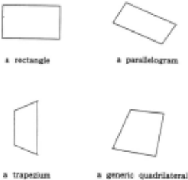
The rectangularity regularity has long been recognized as being of importance. Barnard (1983) computes the pla nar orientation of a rectangle from its image, a quadrilat eral, under perpspective projection. Kanatani (1986) dis cusses how to compute spatial orientations of the faces of a rectangular trihedral polyhedron. Xu and Tsuji (1987a,b) extends this regularity to curved surfaces and proposes the LOC (line of curvature) regularity to recover shape of curved surfaces. In this paper we give a unified and detailed account of interperting quadrilaterals in image as rectangles in space under both orthographic and perspec tive projections.
2.2 The focal point and rectangle orientation
In the followin)1; we discuss how and to what extent the
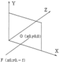
3-D orientation of a quadrilateral is determined by incorpo rating the rectangularity regularity. The coordinate system we assume, as shown in Fig. 2, is different from those we usually use, in that the coordinate origin is located on the image plane and in that the z-axis is independent of the focal point, which has the coordinates ( xO, yO,- f). Both the "image center" ( xO, yO) and the focal length fare then to be determined in the process of interpretation. While the camera system is an objective one if the image is a real one, it is a subjective one if the image is a hand-drawn figure.
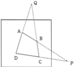
What is known is a quadrilateral in the image, and what is to be known is the orientation of the rectangle that projects that quadrilateral, and the location of the focal point, but not the distance or size of the rectangle. Let the four corners of the quadrilateral be A, B, C and D, as shown in Fig. 3. Extending the segments AB and
~------------~
Fig. 3 Extending the laterals we have two vanishing points P and Q.
CD, we have the intersection P (x1,y1). Since AB and CJ? are the images of two parallels, P is the vanishing pomt of the parallels. Similarly, extending the segments BC and DA, we have the intersection Q (x2,y2), which is also a vanishing point, of the other group of parallels. P and/or Q approach infinity if the corresponding image segments are parallel.
A straightforward demonstration of the concept of vanishing point is that the line connecting the focal point and a vanishing point is parallel to the parallel lines that give rise to that vanishing point. As shown in Fig. 4, we know that PF is parallel to A'B' and C'D', and QF is par~llel to B'~' and D'A'. Since A'B'C'D' is a rectangle, PF 1s perpendicular to QF. The plane determined by PF and QF is parallel to the plane on which the rectangle lies, and thus the orientations of the two planes are identical.
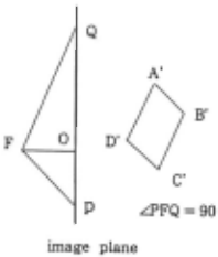
The segments PF and QF can be expressed in vector form as (x1-x0, y1-y0, f) and (x2-x0, y2-y0, f), respectively. From the perpendicularity, the inner product of the two vectors is zero. By this equation F can be either deter mined or at least constrained. Once F is determined the plane normal of (let it be called n) can also be deter~ined ~the outer product of PF and QF. In the following, we d1scuss three cases of PF and QF: (1) neither P nor Q approaches infinity; (2) either P or Q approaches infinity; and (3) both P and Q approach infinity.
(easel) If both P and Q do not appproach infinity, then the quadrilateral is a generic one. From the perpen dicularity of PF and QF we have
Clearly, f (J > 0) can be determined as
This equation describes a hemisphere with a diameter PQ, on which F is constrained to lie, as shown in Fig. 5. For f to have a solution, the point 0 ( xO, yO, 0) must satisfy the following inequality:
This means that 0 must lie inside the circle with PQ on the image plane. When Q reaches the midpoint of PQ, all of PO, QO and FQ become radii of the hemisphere, and f has the maximal value, half the length of PQ. To determine F completely, however, we have to first know where the attention is oriented; i.e., where 0 is. If there are three or more quadrilaterals in a real image, then P can be determined as the intersection point of the hemispheres corresponding to the quadrilaterals (see Section 4 for a spe cial case.) A prerequisite to this solution is that the hemi spheres do have a common point; i.e., the image is a real one. However, as in hand-drawn figures, quadrilaterals are usually produced by individual attentions. Consequently, they should be, and can only be, perceived separately. One reasonable choice for each quadrilateral is the intersection of the two diagonals, which is the centroid of the corre sponding rectangle in space, if the centroid is within the circle with a diameter PQ. As mentioned above, the max imal value for f is half the length of PQ. Trially, the closer to a parallelogram the quadrilateral is, the greater f is. On the other hand, humans prefer long focal lengths in
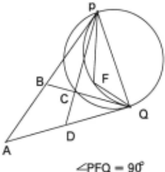
LPFQ = 90'
Fig. 5 F lies on the hemisphere with a di ameter PQ.
the p:rception of figures. This answers why a parallelo gram 1s more oft~n used to represent a rectangle, and why a parallelogram 1s more easily perceived by our eyes as a rectangle.
(Cas_e 2) If ?ne of P and Q approaches infinity, then the quadnlateral1s a trapezium. Without loss of generality suppose that P approaches infinity, while Q does not. PO ~x1~x0, y1-yO) can be expressed by (a, b) asP approaches mfin1ty. Addmg the z-component, PF can be expressed by ~a, b, c), where a, b and c are all constants. c approaches 0 1f f does not approach infinity, and c may still be 0 even if f doe~ approach infinity. Can f approach infinity? Suppose that 1t does. Then clearly BC is parallel to DA and their intersection Q also approaches infinity. This ieads to a contradiction. Thus f cannot approach infinity and c equals zero.
then From the perpendicularity of PF and QF, we have
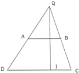
This equation constrains OQ to be perpendicular to AB and CD; i.e. , 0 must lie on the line perpendicular to AB and CD drawn from 0. Let us call the line IQ (Fig. 6). Since f is free, F is constrained to lie on the plane that projects onto the image as IQ. When 0 is located at Q, the orientation is completely determined by the orientations of AB and CD as (b, -a, 0).
(case 3) If both P and Q approach infinity, then the quadrilateral is a parallelogram or a rectangle. In this case, PO is parallel to AB and CD, and QO is parallel to BC and DA. 0 is actually not constrained. Suppose that the orientations of PO and QO are expressed by (a, b) and (a', b'), respectively. Adding the z-components, PF and QF are expressed by (a,b,c) and (a',b', c'), respectively. a, b, c, a', b' and c 'are all constants. Both c and c 'approach 0 iff does not approach infinity, and c and c' may still be 0 even iff does appoach infinity. l,From the perpendicularity of PF and QF, we have
A special case is that ABCD is a rectangle;
Three cases are possible:
If one of c and c' is not zero, then f approaches infinity; the projection can only be orthographic. If both c and c' are zero, then f is not constrained; the projection can be either orthographic or perpspective. In this case, the rect angle normal can be determined as (0,0, 1); the rectangle is parallel to the image plane.
3. Quadrilaterals as Faces of a Rectangular Polyhedron
Any figures can be interpreted at two diferent levels: the geometrical level and the perceptual level [Sugihara, 1986] . While interpretations at the geometrical level must strictly obey mathematics, interpretations at the percep tual level show humanlike flexibility. Interpretations at two levels may be fairly different. We first deal with the geometrical level.
It can be mathematically proven that a trihedral poly hedron with quadrilateral faces is a hexahedron. If all the faces are parallelograms, the hexahedron becomes a par allelepiped. If the parallelograms are rectangles, then the parallelepiped becomes a rectangular polyhedron.
Trivially, When a parallelepiped is projected onto an image from a general position, orthographically or perspec tively, at most three of its six faces are visible. All the three visible faces in the image are parallelograms if the projection is orthographic, and are not if the projection is perspective.
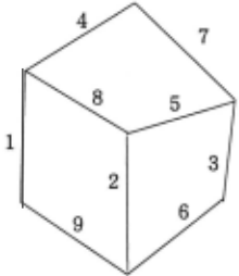
Now we consider the inverse problem - how to in fer the original object from its non-degenerate image. We are given three quadrilaterals, every two of which have a common edge - this condition is sufficient to define their interrelations. Since there are three common edges, the total number of edges is 9 (=12-3). They can be grouped into three, each of which has three non-intersecting edges, as e1-e2-eS, e4-e5-e6, e7-e8-e9 shown in Fig. 7. The first condition for the figure to mean a real object is that the edges of each group meet at a common point , which may approach infinity.
In the following we try to find the conditions for the three quadrilaterals to be simultaneously interpreted as
rectangles.
If none of the three intersection points approaches in finity, we need only to examine whether or not the three hemispheres, each of which is determined by two common intersection points as the vanishing · points as described in the last section, have a common point; i.e. , whether or not the following three equations have a solution for ( xO, yO, f).
where (x1,y1), (x2,y2) and (x3,y3) are the three intersec tion points. Taking the differences of every two equations, we have
These equations mean that (xO, yO) is the orthocenter of the triangle formed by the three intersection points (x1, y1), (x2, y2) and (x3, y3). Thus, fortunately, the three hemispheres always have a common point.
If one of the three intersection points approaches in finity, then we have the following three equations,
where (a,b) is the orientation vector, and (x1,yl) and (x2, y2) are the coordinates of the other two intersection points. The difference of the first two equations means that the parallel edges are perpendicular to the line linking the other two intersection points. The focal point is not com pletely determined, but constrained to lie on a semicircle, whose two end points are the two intersection points, and the plane on which the semicircle lies is perpendicular to the image plane.
If two of the three intersection points approach infinity and the other one does not, then one of the three quadrilat erals must be a rectangle. As discussed in Section 2, if two vanishing points approach infinity, then the corresponding image quadrilateral is a parallelogram or a rectangle. If the parallelogram is to be interpreted as a rectangle in space, then the projection must be orthographic. If the projection is orthographic, then all rectangles in space are projected as parallelograms in image. Thus, if two of the three in tersection points approach infinity and their corresponding quadrilateral is not a rectangle, then the other one must also approach infinity. As described in Section 2, if a space rectangle is parallel to the image plane, then it is projected as an image rectangle under the perspective projection. If it is a face of a rectangular polyhedron, then the other two visible faces are projected as generic quadrilaterals, with the corresponding vanishing points not approaching infin ity.
If all the three intersection points approach infinity, then the projection is orthographic. The condition for a rectangular polyhedron interpretation is that the following three equtions have a common solution for c1, c2 and c3.
where Vl = (al,b1), V2 = (a2,b2) and V3 (a3,b3) are the orientation vectors of the three groups of parallel edges. Easily we have
The condition for a solution of cl, c2 and c3 is that all the three inner products are negative - all the three angles around the central corner are greater than 90 degrees. It is impossible that two of the three inner products are positive and the other one is negative, because otherwise one of the angles around the central corner would be greater than 180 degrees, reducing three quadrilaterals to two.
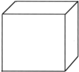
While interpreting figures at the geometrical level is strictly governed by mathematics, it must possess certain degree of flexibility at the perceptual level; otherwise it would not work on hand-drawn figures in a humanlike way [Sugihara, 1986]. Both the condition for a real object inter pretation and the condition for a rectangular polyhedron interpretation derived at the geometrical level have te be changed. First, in a hand-drawn figure, it is too strict a condition that the three edges of each group, when ex tended, meet at a common point. Also, the parallel edges are nearly parallel. Secondly, as given in Fig. 8, even when one of the three angles around the central corner is ex actly 90 degrees, the figure is still perceived as a rectan gular polyhedron (the interpretation is impossible math ematically.) A feasible explanation for this fact is that the individual quadrilaterals are first interpreted separately (as rectangles) and then integrated as faces of a rectangu lar polyhedron in a less strict way than at the geometri cal level. This kind of perception seems quite ubiquitous. When drawing a man or an animal, children usually put together a frontal view of the face and a side view of the body. But the flexibility has its limit; if one of the three angles around the central corner is more than 90 degrees, the figure is no longer perceived as a rectangular poly hedron (Fig. 9,) but an ordinary parallelepiped [Perkins, 1983; Kanade & Kender, 1983].
Lastly, although the rectangular polyhedion interpre tation is mathematically correct if all the three intersection points of each edge group do not approach infinity, it does not always agree with human perception, if the orthocen ter of the triangle formed by the three intersection points is far away from the figure itself.
4. The Gravity Regularity
Everything, including the perceiver itself, is attracted by gravity. As a consequence, objects must be supported by something. It is usually perceived to be the ground, perpendicular to the direction of gravity, if no evidence indicates otherwise. The gravity regularity is generalized from this universal fact. Unlike the rectangularity regularity, it is a natural regularity objectively existing in the external world. So far it has attracted only a little attention. Kanade et al. (1983) analyzes skewed symme try under gravity. Recently, Sedgwick (1987) reports a production system that generates an interpretation of the environment based on linear perspective information and contact relations between surfaces and the ground. Tsuji et al. (1986) also reports a mobile robot that perceives and navigates in an indoor environment with a horizontal flat floor and objects standing vertically on the floor.
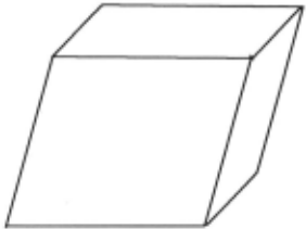
To perceive the world is, in essence, to perceive the relations among the perceiver, the ground and the objects on the ground. By introducing the ground, the relation between the perceiver and the rectangles reduces to the sum of the relation between the perceiver and the ground, and the relation between the ground and the rectangles supported by it. All these relations can be described in either a viewer-centered representation or a world-centered representation based on the ground.
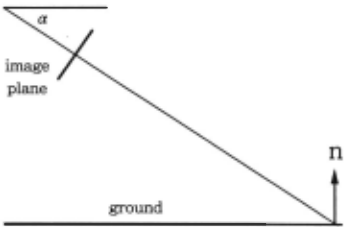
Let the normal of the ground plane be expressed by ng in the viewer-centered coordinate system. ng actually implies the relation between the perceiver and the ground. It is not difficult to find by introspection that we usually assume the following relation to .the ground. Suppose that the camera is originally so set that the optical axis of the camera and the horizontal axis of the image plane are par allel to the ground, as humans look forward while keeping two eyes horizontal. Rotate the camera around the hori zontal axis ofthe image plane by an angle of a (see Fig. 10) as humans look some feet ahead on to the road. Then the normal of the ground plane is projected to be upright onto the image under orthographic projection; i.e. ,
To keep ng upright everywhere, which is desirable, it is necessary to assume the orthographic projection, if a -:f. 0.
Because of the planarity of rectangle and the linearity of its sides, there exist only three kinds of contact rela tions between the ground and a rectangle; (1) the whole rectangle contacts the ground; (2) one of the four sides contacts the ground; and (3) only one of the four comers contacts the ground. When the whole rectangle contacts the ground, the orientation of the rectangle and that of the ground are identical. All the four sides are perpendicular to the ground. When only one side contacts the ground, that side is perpendicular to the normal of the ground. If the rectangle does not stand vertically, it is interpreted to be prevented from falling by something else behihnd it. When only one of the comers contacts the ground, it is most likely that we perceive the rectangle standing vertically.
Which contact relation is perceived is largely depen dant on the assumption of the perceiver's posture. The full contact relation is perceived only if the upper and lower comers are obtuse angles much greater than 90 de grees (Fig. 11a) - i.e., the rectangle is remarkably slanted towards the sky - because we are not used to looking downward (see [Stevens, 1981] for an analysis of the re lation between the image angle of two orthogonal space vectors and the orientation of their outer product.) The comer contact relation is perceived if one of the diagonal, of which the midpoint is the centroid, is vertical in image, and the upper and lower corners are acute angles (Fig. 11 b)
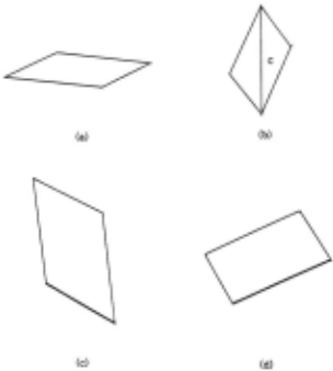
-again because of the posture assumed by the perceiver. The one side contact relation is perceived if the full contact and the one corner contact relations are not . The side that has the smaller angle to the horizontal axis is most likely perceived to contact the ground plane, because we prefer interpretations that are less slanted from the image plane (Fig. 11c,11d).
We do not intend to claim the completeness of the analysis, because perception of one contact relation is not necessarily exclusive of another and the conditions are not completely quantified. Even so, however, if we manage somehow to quantifyt the conditions - e.g., for the full contact relation, the condition may be that the upper and lower angles are greater than 150 degrees - then we can completely determine the contact relations.
The above three contact relations can be respectively expressed as
Before concluding this section, we have one point to note. The orthographic projection is a necessity of the vertical-to-vertical mapping, but it at the same time does not exclude perspective projection for other purposes. The rectangles can still be projected as non-parallelograms. To perceive local shape of an object, the perspective infor mation is required; whereas to perceive the more global relation between the perceiver and the ground, the orthog raphy is required. It is really of interest to observe human's this flexibilty to swing between orthographic and perspec tive projections.
5. Conclusions
We have proposed the rectangularity regularity to be employed in the visual interpretation of quadrilaterals. By this subjective regualrity resulting from the internal struc ture of human perception, quadrilaterals in image are in terpreted as rectangles in space, with the rectangle orien tation and the focal point being completely determined or partially constrained. Projection is perceived altogether. As the second part, we have examined interpreting quadri laterals as faces of a rectanuglar polyhedron at both the geometrical level and the perceptual level. Interpretations at the two levels may be fairly different. Finally we have analyzed the relations among the perceiver (camera,) the ground and the rectangles supported by the ground, and proposed the gravity regularity to derive constraints on the rectangle orientation. Through studying these seemingly simple quadrilaterals we have obtained some insights into the nature of the general problem of interpreting image contours: the rectangularity regularity is just a specific example of the perceptual system's preference of regular forms over irregular forms; while interpreting figures at the geometrical level strictly obey mathematics, interpret ing figures at the perceptual level is much more flexible; and the gravity regularity can be widely applied in differ ent forms.
@inproceedings{ijcai1989p256,
  title     = {Three-Dimensional Interpretation of Quadrilaterals},
  author    = {Xu, Gang and Tsuji, Saburo},
  booktitle = {Proceedings of the Eleventh International Joint Conference on
               Artificial Intelligence, {IJCAI-89}},
  publisher = {International Joint Conferences on Artificial Intelligence},
  editor    = {N. S. Sridharan},
  pages     = {1610--1615},
  year      = {1989},
  month     = {8},
  note      = {Vision and Robotics},
  url       = {https://ijcai.org/proceedings/1989/256},
}
TY - CPAPER TI - Three-Dimensional Interpretation of Quadrilaterals AU - Xu, Gang AU - Tsuji, Saburo T2 - Proceedings of the Eleventh International Joint Conference on Artificial Intelligence, IJCAI-89 PB - International Joint Conferences on Artificial Intelligence PY - 1989 SP - 1610 EP - 1615 UR - https://ijcai.org/proceedings/1989/256 ER -Copied
Machine-readable versions of this paper, for tools and AI agents:





