
On the Operationality/Generality Trade-off in Explanation-based Learning
Proceedings of the Tenth International Joint Conference on Artificial Intelligence. Knowledge Acquisition. Pages 242-247.
© 1987 International Joint Conferences on Artificial Intelligence
Abstract
In this paper we examine the operationalitylgenerality trade-off and how it aft'ects performance of explanation-based learning systems. E:1perience with the ARMS learning apprentice system, presented in the form of an empirical performance analysis, illustrates both aides of the trade-off.
- W. Chafe, "Some Thoughts on Schemata", Theoretical Issues in Natural Language Processing I, Cambridge, MA, 1975, 89-91.
- E. Charniak, "With a Spoon in Hand this Must be the Eating Frame", Theoretical Issues in Natural Language Processing 2, Urbana, IL, 1978, 187-193.
- G. F. DeJong and R. J . Mooney, "Explanation- Based Learning: An Alternative View", Machine Learning I, 2 (April 1986). Also appears as Technical Report UILU-ENG-86-2208, AIRG, CSL, University of Illinois at Urbana- Champaign.
- P. E. Friedland, "Knowledge-based Experiment Design in Molecular Genetics", 79-771, Computer Science Department, Stanford University, Palo Alto, CA, 1979. IJCAI
- B. Gustafson, "Development of Localized Planner for Artificial Intelligence-Based Robot Task Planning System", M.S. Thesis, University of Illinois at Urbana-Champaign, Urbana, IL, October 1986.
- D. McDermott, "Artificial Intelligence Meets Natural Stupidity", SIGART Newsletter 57 (April 1976), 4-9.
- M. L. Minsky, "A Framework for Representing Knowledge", in The Psychology of Computer Vision, P. H. Winston (editor), McGraw-Hill, New York, NY, 1975, 211-277. 248 KNOWLEDGE ACQUISITION
- Mitchell85a]
- T. M. Mitchell, S. Mahadevan and L. I. Steinberg, "LEAP: A Learning Apprentice for VLSI Design", Proceedings of the Ninth International Joint Conference on Artificial Intelligence, Los Angeles, CA, August 1985, 573- 580. IJCAI
- T. Mitchell, S. Mahadevan and L. Steinberg, "A Learning Apprentice System for VLSI Design", Proceedings of the I985 International Machine Learning Workshop, Skytop, PA, June 1985, 123-125.
- T. M. Mitchell, R. Keller and S. Kedar-Cabelli, "Explanation-Based Generalization : A Unifying View", Machine Learning I, 1 (January 1986), 47-80.
- R. J. Mooney and G. F. DeJong, "Learning Schemata for Natural Language Processing", Proceedings of the Ninth lntematiunal Joint Conference on Artificial Intelligence, Urbana , lL., August 1985, 681-687. Also appears as Working Paper 67, AIRG, CSL, University of Illinois at Urbana-Champaign. IJCAI
- R. Popplestone, A. Ambler and I. Bellos, "An Interpreter for a Language for Describing Assemblies", Artificial Intelligence I 4 (1980), 79- 107.
- R. C. Schank and R. P. Abelson, Scripts, Plans , Goals and Understanding: An Inquiry into Human Knowledge Structures, Lawrence Erlbaum and Associates, Hillsdale, NJ, 1977.
- A. M. Segre and G. F. DeJong, "Explanation Based Manipulator Learning: Acquisition of Planning Ability Through Observation", Proceedings of the IEEE International Conference on Robotics and Automation, Urbana, IL., March 1985, 555-560. Also appears as Working Paper 62, AIRG, CSL, University of Illinois at Urbana- Champaign.
- A. M. Segre, "A Learning Apprentice System for Mechanical Assembly", Proceedil1gs of the IEEE International Conference on the Applications of Artificial Intelligence, Orlando, FL, February 1987.
- A. M. Segre, "Explanation-Based Learning of Generalized Robot Assembly Plans", Ph.D. Thesis, Department of Electrical and Computer Engineering, University of Illinois at Urbana- Champaign, Urbana, IL, 1987.
References were extracted automatically from the PDF and may contain errors.
Full text extracted automatically from the PDF; figures, tables and equations may differ. The PDF is the version of record.
1. Introduction
Recent work in explanation-based learning (EBL) baa attracted much attention from the machine learning community [DeJong86,Mitchell86). A number of systems have been and are still being developed in a spectrum of domains from natural language processing [Mooney85), to circuit design [Mitchell85a).
This paper discusses the operationalitylgenerality trade-off and how it arises in EBL in general and the implementation of the ARMS (for Acquiring Robotic Manufacturing Schemata) sys tem in particular [Segre85,Segre87a,SegreR7b). ARMS is a learning apprentice system [Mitcbell85b) that learns to assemble simple mechanical devices using an idealized robot arm. By obsening, analyzing, and generalizing a human planner's solu tion to an anembly episode, ARMS builds a new schema which can be used to synthesize anembly plana for future episodes.
We begin with an intuitive diacunion of the operationality versus generality problem. We then proceed to give a short description of the ARMS system [Segre87b) with emphasis on the generalization procen. Finally, we describe a simple ARMS example to illustrate this important trade-off.
2. Operatioaality versus GeneraHty
E:~planation-baaed learning (EBL) systems are capable of acquiring knowledge from a single example. Using a domain theory, a sample problem solution is analyzed in order to account for how the goal is accomplished. This analysis, or explanation, is generalized to create a new knowledge structure.
If the newly acquired knowledge structure is available to the system, it is said to be operational. If the new structure does not improve the performance of the system in some fashion, it is not worth learning. However, not all operational knowledge is created equal: the coat of using the new knowledge structure is called its operationality. The more operational the structure, the euier (e.g., less upensive) it is for the system to apply it.
The ARMS o;ratem waa d·iped and implemented by the author u part or hia Ph.D. ,...arch at the Univenity or lllinoio at Urbana-ChampaiJn. The au· thor io indebted to Proreeeor G. DeJonJ and the reot or the Coordinated Science Laboratory Artiftcial Intellipnce Reoearch Group Cor their comment. and IUJJO· tiono.
Support ror thia ·-arch W&l provided by a Caterpillar Corporation Graduate Fellowohip, the Air Force Olllce or Scientific Reoearch under Jrant F49620-82-K0009, and tho National Science Foundation under granto NSF-IST-83-17889 and NBF-IST-86-11542.
posit a fixed operationality criterion to specify the level of representation used for the new knowledge structure. They sug gest that a fixed vocabulary be established a priori, so that any new structure described using this limited vocabulary is by definition considered operational.
As pointed out by Mooney and DeJong [DeJong86), there are obvious difficulties involved in· finding such a fixed opera tional vocabulary for any given domain. Even if a fixed opera tionality vocabulary could be specified, there is no guarantee that structures expressed with this vocabulary are easy to apply. As an example, Mooney and Dejong give the following two propo sitions:
PROVABLE("2+2=4") PROVABLE("FERMAT'S LAST THEOREM")
The first is clearly operational, while the second is not. Yet both are described using the same vocabulary.
In any case, the fixed vocabulary approach seems needlessly limiting, especially if one departs from the static classification type tasks of Mitchell et al and considers acquiring problem solving skills. When learning problem-solving skills, the system is acquiring the ability to plan solutions (sequences of operators) to other problems by analyzing a trace of a successful solution.
Mooney and DeJong present an alternative, more dynamic, definition of operationality based on the problem-solving capabil ities of a system. In their view, an EBL system makes previ ously known static concepts operational by learning how to achieve these concepts. For example, the concept of checkmate in the game of chess is easy to describe (a situation where one player's king cannot escape capture) but difficult to operational ize (planning a series of operators to achieve checkmate). A con cept therefore becomes operational only when the system acquires and can index a plan to achieve it.
Making a plan operational makes no statement about the quality of the plan. From our earlier discussion, it is clear that there are many different levels of operationality, levels that will affect system performance. In the next section, we describe an example from the ARMS system which compares two different levels of operationality.
3. The ARMS System
We now turn our attention to an example taken from the ARMS learning-apprentice system [Segre85,Segre87a,Segre87b). ARMS is an EBL system that acquires the ability to plan sequences of robot motions to accomplish assembly of simple mechanisms. A complete description of the system. is far beyond the scope of this paper, however, (1. short overview describing the general structure of the system will be helpful when describing the example.
ARMS learns by unobtrusively observing an expert guide the robot through an assembly task via the robot arm's teach pendant. To the user, this method is indistinguishable from the teach-by-guiding robot retraining method used in most current robot arm installations. In contrast to teach-by-guiding systems which provide for rote memorization of the input sequence, ARMS acquires, from a single episode, the power to plan the assembly of an entire class of functionally similar mechanisms.
The ARMS architecture is that shown in Figure 1. It divides into two elements, the learning element and the perfor mance element, which do not operate concurrently. The two ele ments share domain knowledge which is stored in the form of schemata in the schema library.
The user specifies an assembly by giving a functional goal specification. The goal specification describes the mechanical behavior of the desired assembly, without specifying a physical description. If the performance element can derive a physical goal description from the functional goal specification (the design problem), it then attempts to derive a plan to transform the ini tial world state into a state containing an instance of the design-problem solution (the assembly problem).
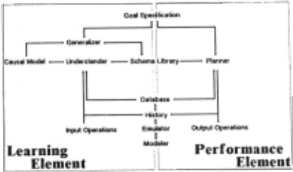
Figure 1
If the performance element fails to find solutions to the design and assembly problems, control is transferred back to the ·user, who now guides the learning element through the assembly process. As the user moves the arm about the workspace, the system observes the user's solution and produces a new schema to use in future problem-solving situations.
3.1. World Model
The ARMS system relies on an emulation of the robot world in order to reason about how pieces fit and move together. This emulator is much like the modeling systems used for com puter graphics and CAD/CAM applications. It is a simple con structive solid geometry (CSG) modeler which represents pieces as the sum and/or difference of primitive volumes.
The modeler is used to model the ARMS gripper and its interactions with the world. 2 It must realize when the gripper is manipulating a piece, what effects these manipulations have on the position of that piece and any piece interactions. The modeler maintains a copy of the world at each time tick by using a storage-efficient mechanism similar to those used for copying sparse matrices.
The rest of the ARMS system does not have direct access to the emulation afforded by the CSG world modeler: rather it only has access to descriptions of this world which are maintained by the database. Any request for world information is shuttled through the database, which manipulates tokens representing relations between elements of the world model. This collection of tokens corresponds to the state of the problem-solving domain. Note that it is the responsibility of the database to uniquify requests so that there is only one copy of a symbolic state to describe a particular partial world state.
3.2. Knowledge Representation
All domain knowledge in ARMS is represented as sche mata. A schema [Chafe75,Charniak78,Minsky75,Schank77) is a general structure which, via the use of slots which can be filled with a variety of different values, can be used to represent a class of similar concepts. A schema is said to be instantiated when all of its slots are bound to constants or other instantiated schemata, in which case it represents a unique concept.
ARMS schemata fall into five different categories:
- Physical object schemata represent the CSG models of the pieces in the domain. While certain limitations are
2 While ARMS has been used to drive a real robot arm [Gustarson86]; ita normal mode or operation involves driving the simulated robot arm in this simu· lated environment.
imposed by the simplicity of the modeler, ARMS can model an infinite set of different pieces.
- State schemata represent the vocabulary with which ARMS reasons about the real world. These are maintained by the database in an on-demand fashion: no state schema is ever generated or otherwise manipulated except as a result of an explicit request by the system. Each state contains tem poral information indicating start and end times for the state. 3
- Constraint schemata are just like state schemata, except that they are time-invariant. Certain aspects of the world are not mutable by applying system operators (e.g., rela tions between sizes of pieces): thus the constraint schemata are maintained more efficiently by the database. Constraint schemata are attached to state schemata to impose restric tions on the values the state schema slots may take.
- Joint schemata are also like state schemata in that theyare maintained by the database and have temporal scope. They come in two ftavors: abstract joint schemata describing the mechanical behavior of two related pieces, and physical joint schemata describing the implementation of the mechanism in terms of interacting surfaces. Together, these joint schemata form the building blocks of the ARMS domain theory.·
- Operator schemata (which include the five primitive opera tor schemata) represent the plans the system can apply. The primitive operator schemata correspond to the idealized ARMS robot arm command set. They provide the lowest level of description for robot motion. Operator schemata describe the context in which they can be applied, as well as what goals they achieve. The composite (e.g., non primitive) operators are recursively defined in terms of other schemata. The system learns this kind of schema, and it is this case we will examine a bit more closely later in our operationality/generality discussion.
3.3. The Performance Element
Inputs to the performance element are:
- The initial state of the world;
- A goal specification given as an abstract joint schema.
The performance element produces a sequence of fully instan tiated primitive operator schemata.
The ARMS performance element begins with a design phase, where a physical joint schema consistent with the func tional goal specification (an abstract joint schema) is derived. This physical joint schema is then used to index into the schema library and select a top-level plan. The planning phase recur sively expands the top-level plan to produce a robot arm com mand sequence which achieves the final state from the specified initial state.
The planning process is a depth-first search through the plan apace defined by the operator schemata (both built-in and acquired) stored in the schema library. This schema planner (similar to the skeletal planner of [Friedland79]) is a simple deaign which selects an abstract plan (in the form of an operator schema) to achieve the· specified goal state, and repeatedly expands it until the process bottoms out with a robot arm com mand sequence. 6
3 Even thou!Jh state ochemu are checked agaiDit the emulator only aa a reault or a requeot, the amount or time spent by the database in satisfying re· queote for oymbolic information about the world accounte for a large portion (in oome eumpleo u much aa 96% of the total) of the computational reoourcea ex· paneled by the ARMS ayotem. While ARMS runs on a aerial machine, this kind of databaae mechanism io a prime example of those algorithms which seem beat ouited to large grain size parallel machines.
· The oyotem ia capable of learning phyaical joint achemata, but the finite oat of abotract joint ochemata ia bui It in (the reader ia referred to [Segre87] for a di.cuuiOD).
3.4. The Learnlnf Element
The learning element is reaponaible for first understanding how the user solved the problem, and then generalizing the observed aolution into something that can be used again later by the performance element. We divide this task into three distinct subtaaka: understanding', verifying, and generalizing.
Inputs to the learning element are:
- The initial state of the world;
- A goal apecification given as an abstract joint schema;
- A sequence of instantiated primitive operator schemata.
The primitive operator schemata are echoed from the teach pen dant of the robot arm being led through the assembly episode by the user. The understander builds a causal model of the exter nal agent's problem solving behavior.
When the user is finished, the system verifies that the func tion of the physical mechanism constructed by the user corresponds to the initial functional goal specification. The verification process relies on a naive kinematic domain theory to analyze the function of a mechanism. This process may result in the acquisition of a new schema via explanation-based specializa tion that operationalizea the functional goal specification and provides a solution to future design problema. (see [Segre87b) for a more thorough description of the verifier).
Next the generalizer produces another schema via explanation-based generalization. This newly acquired schema can then be uaed to solve an entire class of assembly problema which share the same functional goal specification.
In this paper, we give a quick description of the generalizer only: the reader is again referred to [Segre87b) for a more thorough discussion.
3.4.1. The Generalization Process
The generalizer takes as ita input the verified goal specification given by the user and the causal model produced by the underatander. The generalizer produces a new composite operator schema which can be used both in understanding and planning (see Figure 2).
As a result of the verification process, an instantiated ver sion of the user-specified abstract joint schema is tied to a set of physical joint schema tokens in the causal model. These tokens constitute the top-level subgoal set.
We begin by ordering the top-level subgoal set on the basis of a causal dependency analysis. This causal analysis relies on the ARMS. domain theory to determine if there are any ordering dependencies between elements. In short, the limits of travel in the individual subjoints of the mechanism are examined to see if their boundary conditions rely on other subjoints.
5 The ARMS planner otopa at the level of primitive robot arm commando. When driving the robot arm, the primitive operator achemata are expanded into arm-dependent control otatementa: thio is done with an arm·opecific aiJorithm which tekoa robot level atatementa down to the kinematic level. Note that ARMS doee not deal with colliaion avoidance, an active research topic which JOel well beyond the ocope of thia implementation. For now, ARMS auumeo an un cluttered worbpace 10 that colliaion avoidance is not a problem.
1 Apolo1i· to McDermott:
We elaould aYOid, for e:rample, labeling aoy part of our program· aa ·under ..._,,,· It II the job oftbe tezt ac:c:ompaayiac tbe procram to eumiaa carefully Mw macb uadantaadillf il preaent, bow it cot tbere, aad wbat ita limita are [llcDormolt78).
While we often uae the alternate, but le11 illustrative, term j usti{lcation ana/yz.r, which io perhapa more acceptable from McDermott's point of view, thia practice confticta with our goal of deocriptive simplicity.
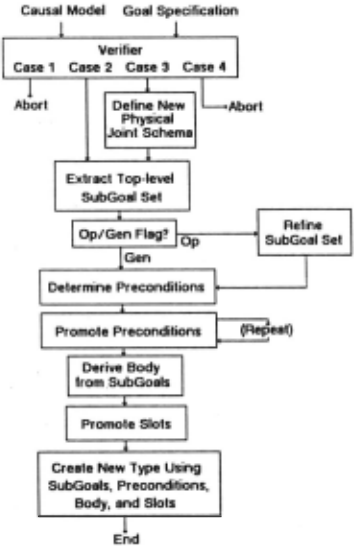
To extract the explanation from the causal model, it is sufficient to follow the pointers established during the under standing process from the (now causally ordered) top-level subgoal set down to the primitive operator inputs. The relevant pointers are those connecting operators to their recursive expan sions. Note that an explanation should also contain pointers to all of the constraint schemata supporting states in the explana tion.
At this point, the generalizer must pick a level of represen tation for the new operator schema. The higher the level of representation, the more generally applicable the new schema will be: however, a price will be paid in the amount of work done by the planner in applying the new schema. The extra work comes from the added levels necessary in the recursive expansion of the plan. Conversely, a more operational new schema will be easier to apply, but less generally applicable.
Depending on the value given by the user to the operationality/generality parameter, the ARMS generalizer expresses a new schema as follows:
- u the abstraction of the top-level aubgoal set, producing a more general new schema (aee Figure 3).
- by descending the explanation structure to a level where all of the aiate schemata are roots of independent subtrees in the explanation (a more operational new schema). The state schemata at this lower level become the aubgoal set of the new composite operator schema. This produces a new aubgoal set which preserves any causal dependency order ings established during the joint analysis (see Figure 4).
Having in this fashion collected a set of subgoals, we now complete the construction of the new operator schema and integrate it into the schema library.
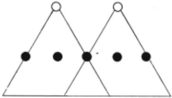
Level with Shared Substructures in Expianation The two elements of the top-level subgoal set in this example are represented as black nodes. Their respective explanation substructures are outlined as triangular subtrees. Shared sub structure is represented by the overlapping sections of the sub trees. When producing the more general new schema, the gen eralizer uses the black nodes of the top-level subgoal eet ae the subgoal set model for the new schema.
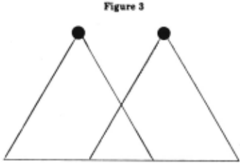
Level with No Shared Substructures in Explanation The two elements of the top-level subgoal set are represented as white nodes at the root position of two overlapping explana tion subtrees. When producing the more operational new sche ma, the generalizer descends into the explanation structure until it can produce a subgoal set (represented here as black nodes) with no shared substructure. This set then becomes the subgoal set model for the new schema.
Figure 4
At first glance, the two schemata do not seem terribly dift'erent. In fact, both new schemata are equally capable of solv ing a aet of similar problems, yielding identical solutions. While their operationality dift'erence is obvious in the levels of recur sive expansion required in planning, their generality dift'erence is not immediately evident.
Closer examination shows that the more general new schema ia better able to integrate subsequently acquired sche mata in its planning behavior. In other words, as the ayatem learns how to do things in other ways, the more general new schema, unlike the more operatipnal new schema, is immediately able to take advantage of this new knowledge.
4. An Enmple
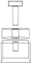
. Consider as an example a mechanism (aee Figure 5) assem bled from three pieces: a washer, a bored block, and a peg. The shaft of the peg is inserted first through the hole in the washer and then into the hole in the block. The washer spina freely about the peg, while the peg fits snugly into the bored block. We call this simple mechanism a widget.
We can describe the widget physically by describing the pieces (call them $Pegl, $Washerl , and $BoredBlockl) and the mating conditions between them (this is the approach taken by moat task level programming systems such aa RAPT [Poppleatone80]). We could also describe this mechanism at a functional level aa a revolute joint, e.g., a single rotational degree of freedom, between $Washerl and $BoredBlockl. Unlike the physical description, the functional description need not expli citly mention $Pegl. In fact , the same functional description would hold for any assembly having the requisite one rotational degree of freedom, regardless of the physical mechanism used to achieve this function.
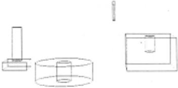
The system is first given the piece descriptions and their initial placements in the workspace (see Figure 6 for an exam ple). When asked to achieve a revolute joint between the washer and the bored block, the system should automatically generate a sequence of fully instantiated (i.e., with all parameters bound) primitive operators which, when applied by the robot arm, transform the initial state into the assembly described above. The sequence should take into account factors such as the proper grasping strategy for each piece, whether pieces are cleared off before attempting to move them, and so on.
Since the system currently has no plan to achieve this con cept (in fact, the system does not yet possess a concept corresponding to this function's physical realization), the system admits defeat, and the user proceeds to show it how to build a mechanism which has the desired functionality. The user guides the system through an assembly episode which reAults in a phy sical assembly that fits the specified goal. Note that the assembly sequence given by the user (input to the system as fully instan tiated primitive operators) need not be an optimal sequence, but simply effective in accomplishing a physical instantiation of the functionally specified goal.
The system verifies, using its domain theory, how the phy sical assembly realized instantiates the desired functional goal. During the verification process, a new concept corresponding to this physical realization of the functionally specified goal is acquired.
If the verifier terminates successfully, the generalizer pro duces either a more general or a more operational new schema which can be used to solve similar problems.
5. Results
In this section, we present some empirical results collected from the ARMS system. ARMS is implemented using the object oriented language LOOPS, which is in turn constructed in INTERLISP-D. These results were collected on a Xerox 1109 Lisp Machine running the Koto release of INTERLISP-D and the Buttress version of LOOPS. The 1109 has 3.5 megabytes of main memory, a 43 megabyte hard disk drive, and a hardware floating point coprocessor.
Performance of the system is adversely affected during these tests by the information-collecting mechanism. The system suffers a factor of eight slowdown while collecting these statis tics. However, since our only interest here is in comparing one example with the other, the slowdown effects are not relevant.
Initial State 1
The robot gripper is locatM in the center of the picture with fingers closed and pointed down. $BoredBlockl is to the right, $Pegl is to the left, and $Washer! is in the foreground just left of center. The functional goal specification is given as an abstract joint schema $RevoluteJoint[$BoredBlockl , $Wash erl).
Figure 6
5.1. Learning Episode 1
Given the initial configuration shown in Figure 6, the sys tem is presented with a sequence of 12 primitive operator sche mata which .complete the assembly of the widget shown in· Fig ure 3. The system constructs a new, more operational, schema which can plan the assembly of this and other functionally simi lar mechanisms.
| Table 1 Learning Episode 1 | |
|---|---|
| Length of observed sequence Causal model size (tokens) Explanation size (tokens) | 12 159 144 |
| Number of database queries Number of tokens created Number of requests issued Number of slot reads Number of slot writes Total CPU time (seconds) | 1129 2090 110913 103892 4581 |
| Generalizer time (seconds) | 2039.1 40.9 |
The size of the causal model and the explanation are given in terms of tokens, where each token represents a schema instance. This is a pretty good measure of the difficulty of the example: the larger the number, the more complex the analysis or the plan.
The number of database queries, tokens created, requests issued and slot manipulations are a good general indicator of how much work is performed by the system.
The total CPU time reflects the time for emulating, under standing, verifying, and generalizing the example. Also provided is the CPU time for generalization alone.
5.2. Learning Episode 2
This example is identical to Learning Episode 1, except that the more general new schema is constructed.
As expected, the results shown here are almost identical to the results of the previous, identical, episode. The only difference is in the time spent on generalization. The extra analysis required to produce the more operational new schema is clearly evident in the greater CPU time for generalization in the opera tional case. This is consistent with expected behavior.
| Table 2 Learning Epi1ode 2 | |
|---|---|
| Length of observed sequence Causal model size (tokens) Explanation size (tokens) Number of database queries | 12 159 144 |
| Number of tokens created Number ofrequests issued Number of slot reads Number ofslot writes Total CPU time (secondi) | 1117 2072 109639 102380 4573 |
| Generalizer time (seconds) | 2047.8 26.4 |
5.3. Problem-Solving Epi1ode 1
We again present the system with the initial configuration of Figure 6. The system is asked to produce a revolute joint between $BoredBlock1 and $Washer!. The system solves the design problem and then applies the more operational version of the new schema to the assembly problem, generating a 12 step solution.
| Table 3 Problem-Solving Episode 1 | |
|---|---|
| Length of planned sequence Planner search tree size (tokens) Planner subtree size (tokens) Number of database queries Number of tokens created Number of requests issued Number of slot reads Number of slot writes | 12 146 95 |
| 1003 | |
| 1554 | |
| 84754 | |
| 92593 | |
| 2987 | |
| Total CPU time (seconds) | 1724.5 |
5.4. Problem-Solving Episode 2
This example is identical to Problem-Solving Episode 1 (see Figure 6), except that the new schema being applied is the more general version. We therefore expect this example to be less efficient, since the planner must work harder when applying a more general schema.
| Table • Problem-Solving Epi1ode 2 | |
|---|---|
| Length of planned sequence Planner search tree size (tokens) Planner subtree size (tokens) Number of database queries Number of tokens created Number of requests issued Number ofslot reads Number of slot writes | 12 151 138 1340 2044 118962 |
| 139695 | |
| 3661 | |
| Total CPU time (seconds) | 2498.8 |
The system generates the aame solution as in Problem· Solving Episode 1. The solution, however, is more expensive to generate as indicated by the number of tokens generated and requests issued This behavior is also evident in the total CPU time figure (42 minutes as compared to 29 minutes in the other case). In addition, the planner subtree is a bit larger: but since the additional nodes tend to be at the highest level of abstrac· tion, the increase in CPU time tends to be more than linear in the increased subtree size.
-------------
Initial State 2
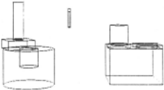
The robot gripper is located in the center of the picture with fingers closed and pointed down. $BoredCylinderl is to the left, with $Pegl atscked on top of it. $Peg3 and $Washer2 are stacked (from left to right) on top of $Biockl on the right side of the workapace. The functional goal specification is the same ae in Initial State 1.
Figure 7
5.5. Problem-Solving Episode 3
This problem-solving episode demonstrates the power of the system in planning the assembly of physically different yet func tionally similar mechanisms. The system is asked to plan for a revolute joint between $BoredCylinder1 and $Washer2. There is no mention of $Peg3: the system must decide for itself which of the other pieces in the workspace can be used to achieve a physi cal instance of the functionally specified goal. The initial state is shown in Figure 7.
In this eumple, we are asking the system to deal with not only a more complicated initial starting configuration, but also the system must construct a functionally specified assembly from physically different pieces.
| Table 5 Problem-Solving Episode 3 | |
|---|---|
| Length of planned sequence Planner search tree size (tokens) Planner subtree size (tokens) | 18 204 133 |
| Number of database Number of tokens created issued | 3128 |
| queries | 1753 |
| Number of requests | 174732 |
| Number of slot reads | 184900 |
| Number of slot writes | 5433 |
| Total CPU time (seconds) | 3533.3 |
5.6. Problem-Solving Episode 4
Problem-Solving Episode 4 is identical to Problem-Solving Episode 3 (see Figure 7). The system supplies the identical solu tion, but at greater computational expense. This is consistent with expected behavior.
| Table 6 Problem-Solvin& Episode 4 | |
|---|---|
| Length of planned sequence Planner search tree size (tokens) Planner subtree size (tokens) | 18 215 194 |
| Number of database queries Number of tokens created Number of requests issued Number of slot reads Number of slot writes | 2357 3952 256358 287017 |
| 3427 | |
| Total CPU time (seconds) | 5257.7 |
1;,
'!
6. Conclusion
In this paper, we have provided an overview of the operationality/generality trade-off for explanation-based learning systems. We have described one approach, that of the ARMS learning-apprentice system, for characterizing the operationality of a new schema based on the structure of the explanation itself. Finally, we described an experiment that provides preliminary empirical evidence of the importance of this trade-off.
What we are really dealing with is a set of plans covering a spectrum of operationality/generality characteristics. It is up to the system designer to decide what the best level(s) of opera tionality are for a given system. Given that there is no single solution, the best we can hope for is to understand the problem well enough to decide where on the continuum a given system's generalizer should reside.
@inproceedings{ijcai1987p49,
  title     = {On the Operationality/Generality Trade-off in Explanation-based Learning},
  author    = {Segre, Alberto Maria},
  booktitle = {Proceedings of the Tenth International Joint Conference on
               Artificial Intelligence, {IJCAI-87}},
  publisher = {International Joint Conferences on Artificial Intelligence},
  editor    = {John McDermott},
  pages     = {242--247},
  year      = {1987},
  note      = {Knowledge Acquisition},
  url       = {https://ijcai.org/proceedings/1987/49},
}
TY - CPAPER TI - On the Operationality/Generality Trade-off in Explanation-based Learning AU - Segre, Alberto Maria T2 - Proceedings of the Tenth International Joint Conference on Artificial Intelligence, IJCAI-87 PB - International Joint Conferences on Artificial Intelligence PY - 1987 SP - 242 EP - 247 UR - https://ijcai.org/proceedings/1987/49 ER -Copied
Machine-readable versions of this paper, for tools and AI agents:





