
Hardware Diagnosis as Program Debugging
Proceedings of the Tenth International Joint Conference on Artificial Intelligence. Knowledge Representation. Pages 524-525.
© 1987 International Joint Conferences on Artificial Intelligence
Abstract
Horn clauses provide a useful framework for writing executable structural representations for digital circuits. This paper discusses how these representations can be used to diagnose faulty circuits using algorithmic program debugging techniques developed by Shapiro. The sound theoretical basis of these techniques Is one of the major advantages of this approach. This framework also provides a new perspective on some of the hardware diagnosis techniques suggested In the literature.
- Clancey, W.J., "Classification Problem Solving", in Proc. AAAI-84. 1984, pp. 49-54.
- Clocksin, W.F., "Logic Programming and digital circuit analysis ", to appear in J. Logic Programmi~ (1987).
- Davis, R., "Expert Systems: where we are and where do we go frotn here", AI Magazine, Summer 1982.
- Davis, R., et. al., "Diagnosis based on description of structure and function ", Proc. AAAI-83, 1983, pp 137-142.
- Genesereth, M.A., "The use of design description in automatic diagnosis", Artificial Intelligence 24 (1984) 411-436.
- Hamscher,W. & R. Davis, "Diagnosing circuits with states: an inherently underconstrained problem ••, ~roc =--~AAI-84.
- Shapiro, E.Y., Algorithmic Program Debugging , MIT Press, Cambridge, Mass. (1982).
References were extracted automatically from the PDF and may contain errors.
Full text extracted automatically from the PDF; figures, tables and equations may differ. The PDF is the version of record.
ABSTRACT
Horn clauses provide a useful framework for writing executable structural representations for digital circuits. This paper discusses how these representations can be used to diagnose faulty circuits using algorithmic program debugging techniques developed by Shapiro. The sound theoretical basis of these techniques Is one of the major advantages of this approach. This framework also provides a new perspective on some of the hardware diagnosis techniques suggested In the literature.
I INTRODUCTION
Even after substantial effort the problem of diagnosing hardware faults remains a major research Interest. Earlier work In this area was based on the empirical approach, I.e. having statically complied fault dictionaries and various ways of searching through them. This approach, which has been widely used In many conventional expert-systems, Is based on the heuristic classification technique (1 ]. The limitations of the classification-based approach to diagnosis have long been identified [3]. The main problems with this approach, e.g. the lack of flexibility and extensibility, arise due to mixing control information with domain knowledge. An alternative model-based approach has been suggested by Davis [4] and Genesereth [5]. This approach uses explicit representation of the structure and behavior of the device; and Instead of scanning a fault dictionary the principle of violated expectation (4] Is used to localise the fault.
A fundamental problem with the research in model-based hardware diagnosis has been Its distinct lack of theoretical foundations. With recent work in the field of software debugging which has strong theoretical motivation, this absence becomes even more conspicuous. Not only has this led to a proliferation of seemingly different techniques, it has also shrouded the fundamental problems that need to be addressed before these techniques can be scaled up to handle real devices. The relationship between hardware and software being well known (at least at the coarse level of hardware . granularity) there is a potential relationship to be explored between diagnosing hardware and debugging software.
This paper explores the relationship between algorithmic program debugging based on the model-Inference system (MIS) built by Shapiro [7] and the techniques for hardware diagnosis using device models proposed Independently by Genesereth and Davis. As MIS can be best illustrated in pure-PROLOG, we first describe how to represent a digital circuit as a PROLOG program. The next section summarises the program debugging component of the MIS and explains
HARDWARE DIAGNOSIS AS PROGRAM DEBUGGING
Ajay Gupta
Hewlett-Packard Laboratories
Bristol Research Centre
Filion Road, Bristol BS12 6QZ, UK
Email: ag<CPhplb.csnet
the terms used later in the paper. Then we . present two obnrvations that enable hardware diagnosis to be conducted by the contradiction backtraclng in MIS. We illustrate the method on an example used by [5). Then we illustrate how sequential circuits can be handled in this framework. Finally we explain how the contradiction backtracing technique relates to the techniques that have been proposed by Davis and Genesereth.
II CIRCUIT·DESCRIPTION IN PROLOG
Circuits can be· represented in pure-PROLOG by identifying a clause with a hardware module. The head of the clause gives the black-box view of the module - the predicate beiny the type of the module and the arguments being . the ports of the module. This represents the top-level abstraction of the device, expressing its input-output behaviour with no reference to its internal structure. For instance a full_adder is represented as:
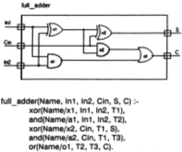
The internal structure of a module consists of its submodules and the connections between them. This information is represented by the body of the clause that describes the module. The body consists of a set of terms each representing a submodule, and the connections between these submodules are represented by sharing a variable between the terms. Note that the order of submoduies in the body of a module is completely Irrelevant. This method of representing circuits in pure-PROLOO has been called the definitional method by Clocksin (2]. We extend this representation to require that each module carries its name as Its first argument. The reason for this requirement, which are related to the diagnosis problem, will become clear later.
The above definition reflects the structural composition of the full adder, and at the same time Its execution under a PROLOG interpreter simulates the behaviour of the device.
This representation also captures the hierarchical nature of the device, where hierarchy is achieved by including a call to a module in the definition of a higher-level module. The lowest level of the hierarchy consists of the basic elements represented as a set of unit clauses. For instance the logic gates can be represented as:
xor(Name,O,X,X).
xor(Name,1 ,1,0).
xor(Name,1,0,1 ).
and(Name,O,_ ,O).
and(Name,1,X,X).
Ill OVERVIEW OF MIS
The program debugging techniques in MIS apply when the programmer has a program P that on input x returns an Incorrect output y. The goal of debugging is to locate the erroneous modules and possibly show 'how' they are failing. It is required that there exists a mechanism that can serve as an oracle for answering the queries of the form:
'is y a correct output of module P on input x' , and 'what is a correct output of module P on input x'.
These two types of oracle have been termed ground and existential oracles respectively. Normally the programmer is expected to be able to answer such queries, hence act as the oracle. If the oracle can be mechanised debugging becomes completely automatic.
If M is an interpretation for a procedure P, an oracle simulation of P on x with M is defined as a computation of P on input x where every procedure immediately called by P on input x is simulated by a call to an oracle for M. The goal of an oracle simulation is to isolate the execution of a procedure call from the possible errors in subordinate procedure calls. A procedure P is correct in M if, for any x, the output of any oracle simulation of P on x with M is correct in the model M. If a procedure is incorrect then there is some x such that oracle simulation of P on x returns an output y which is not correct in M. Such a simulation gives the desired counterexample to the correctness of Pin M.
The simplest algorithm to debug an incorrectly terminating program P on input x is based on traversing the tree of procedures invoked on the input. The parent relation in the tree reflects the procedure invocation relation, and the sons in the tree are ordered according to the order in which the procedures are invoked. If a procedure P' on input x' returns an output y', the algorithm calls the ground oracle to check its correctness. If the oracle returns 'yes' the simulation continues. The procedure that returns 'no' is the incorrect procedure. The order in which the algorithm queries the oracle corresponds to the post-order traversal of the procedure invocation tree. Various optimisations that attempt to minimise the number of queries asked have also been proposed (7].
IV HARDWARE DIAGNOSIS IN MIS
In order to apply the program debugging techniques to hardware diagnosis we have to address two problems. First, in the case of software modules once a module has been tested, it can be used or called in any number of places without further verification. On the other hand, we know that just because one and-gate has been shown to be fault-free does not mean every and-gate will be behaving correctly. This problem can be hand.led by ensuring that each physical instance of a module has a unique name as part of its definition. It is for this reason we require that each module carries as its first argument a name, part of which is built using Its parent's name.
Secondly,in the case of program debugging, the debugger has the incorrect program, and the oracle, usually the programmer, has the information about the correct or intended behavior. But in the case of faulty hardware the debugger has complete knowledge of the intended behavior from the design descriptions, but the faulty theory is embedded in the device under diagnosis from which it can be extracted only by making some measurements. Thus there is a complete duality between the knowledge available with the program debugging and hardware diagnosis systems.
In order to map hardware diagnosis onto program debugging we only need to recognise that the correctness of a theory is defined in reference to a model. Thus diagnosis turns out to be finding the discrepancy between the theory and the model. Whether the model or the theory is 'correct' in the real world is irrelevant for diagnosis. We can now treat the incorrect or faulty device as the intended behavior, i.e. the model, and its design description as the incorrect theory to be debugged. In this framework the device under diagnosis acts as the oracle - both functional and ground, that can be used for answering the queries while 'diagnosing' the designed behavior.
With these two observations, fault-diagnosis as proposed by Davis (3,4] and Genesereth [5] can be reproduced by the diagnosis algorithms in MIS. For details of the debugging algorithms readers are referred to [7]. The following script shows the queries asked to diagnose a fault. A goal such as:
7- fp(fadder(fa, 1 ,0,0,1,1 ), X).
is a query to find the clause that would explain the behavior of full_ adder that results in (1, 1) on inputs (1,0,0). The debugging algorithm attempts to find the culprit module by querying the oracle. This is very similar to signal tracing which Davis and Genesereth have suggested. Following is a trace for this simple example where the faulty module is and(a2) :
Query: xor(fa/x1 , 1, 0, 1 )7 1: y.
Query: and(fa/a1 , 1, 0, 0)7 1: y. Query: xor(fajx2, 1, 0, 1 )7 1: y. Query: and(fa/a2, 0, 1, 0)7 1: n. X= and(faja2, 0, 1, O):-true.7 yesOracle's response is indicated in bold. The counterexample found indicates the 'faulty' module and how its behavior differs from the actual behavior. Notice that although this 'faulty' behavior refers to module in the design-description, in practice we would really need to modify the oracle so that it matches the intended behavior.
V DIAGNOSING CIRCUITS WITH STATES
So far we have only considered combinational circuits · circuits whose output is a function of current input signals only. In sequential circuits, on the other hand, the output is determined by the order in which the signal is applied, thus the history is important for the behavior. Sequential circuits can be of two types: unclocked (asynchronous) or clocked (synchronous). Asynchronous circuits can be modelled only at an abstraction higher than the time-domain in the definitional method. For synchronous circuits additional arguments are required to represent history. For example, a JK-IIip flop will
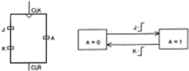
%call pattern: jkff(Name,CLK,J,K,CLR,A,State).
jkff(N,C,_ ,_, 1 ,0,_). % high CLR clears the output
jkff(N,-,_,_,O,State,State).% falling edge
jkff(N,+,J,_ ,O,J,O).
% rising edge
jkff(N,+,_,K,O,K, 1 ).
In order to simulate such a model of synchronous circuits the top-level input and output ports need to represented as a sequence of values, i.e. a list, representing the data at each clock-tick. Consider a synchronous parity checker:
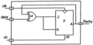
pcheck(Name,CLK,CLR,Data,Parity,State) : xor(Namefx1 ,Data,State,J), jkff(Name/j1, CLK, J, K, CLR, Parity, State).
To simulate its behaviour over a period of time, we need to recurse on the clock-ticks:
simulate _pc([J, (],(], (],_). simulate_pc([Cik 1 Clks],[Cir 1 Clrs],(D1 1 Ds],(P1 I Ps],State) : pcheck(pc,Cik,Cir,D1 ,P1 ,State), simulate_pc(Ciks,Cirs,Ds,Ps,P1 ).
Once a circuit has been represented in this manner, the main distinction between synchronous and combinational circuits is whether the definition is recursive or not. II is clear that oracle simulation is a safeguard even from errors in recursive calls to the procedure being simulated. For instance, an example of correct simulation is:
If in a scenario we actually get P = [0,1 ,0,0], because of the stuck-at-0 on pin1 of xor(x1 ), the following diagnosis trace will be observed:
?- fp(simulate_pc([+,+,+,+],[1 ,0,0,0],[0, 1 ,0,1 ],(0, 1,0,0],_),X).
Query: xor(pcfx1, 0, 0, 0) ? I : y.
Query: jkff(pcfj1 ,+, 1 ,0,0,0,0) ? I: y.
Query: pcheck(pc,+, 1 ,0,0,0) ? 1: y.
Query: xor(pcfx1 ,0, 1 ,1) ? I : y.
Query: jkff(pcfj1 ,+,0,1,1,1 ,0) ? I: y.
Query: pcheck(pc,+,0,1, 1 ,0) ? I: y.
Query: xor(pcfx1,1,0, 1) ? I: n.
VI CONCLUSIONS & FURTHER WORK
There are two approaches to hardware diagnosis depending on whether the diagnosis system has complete or pa1 tial observability of signals in the device under diagnosis. In this paper we have demonstrated that in the framework where the diagnosis mechanism has complete observability, i.e. the oracle can take a measurement at any poi11t in the device under diagnosis, hardware diagnosis can be conveniently modeled .as algorithmic program debugging. This approach provides us a powerful framework for studying automatic fault correction as well . For instance, Davis (3] recognises different kinds of failures that need to be considered commonly in hardware diagnosis:
stuck-ats or floating pins short-circuits ports in unintended directionality
In the framework of MIS each of these failures would constitute a refinement relation [7]. We need to define the refinement relations for different kinds of hardware failures and the techniq1,1es for searching the refinement trees generated by them.
The ability to take measurements at arbitrary points in the device is possible only in a laboratory environment. In the field however the devices have a limited observability because only the signals coming out on the output ports can be seen. Partial observability adds a fundamentally new dimension to fault-diagnosis. One approach would be find techniques to regain the effects of that resolution. In this regime, the crucial issues relate to the problem of test-generation.
There are important issues to be addressed in order to make the definitional representation of circuits easier to use. In particular the clocks do not hierarchically abstract, so the behavior of the circuit at the top-most level still needs to be looked at the lowest level of clock granularity. We need gradual temporal zooming-in appropriate to the behavior of the module under study [6].
ACKNOWLEDGEMENTS
Thanks are due to John Lumley, Bill Clocksin, Bill Sharpe and Andy Buchanan for their valuable comments.
@inproceedings{ijcai1987p104,
  title     = {Hardware Diagnosis as Program Debugging},
  author    = {Gupta, Ajay},
  booktitle = {Proceedings of the Tenth International Joint Conference on
               Artificial Intelligence, {IJCAI-87}},
  publisher = {International Joint Conferences on Artificial Intelligence},
  editor    = {John McDermott},
  pages     = {524--525},
  year      = {1987},
  note      = {Knowledge Representation},
  url       = {https://ijcai.org/proceedings/1987/104},
}
TY - CPAPER TI - Hardware Diagnosis as Program Debugging AU - Gupta, Ajay T2 - Proceedings of the Tenth International Joint Conference on Artificial Intelligence, IJCAI-87 PB - International Joint Conferences on Artificial Intelligence PY - 1987 SP - 524 EP - 525 UR - https://ijcai.org/proceedings/1987/104 ER -Copied
Machine-readable versions of this paper, for tools and AI agents:
 Welcome
 Future Conferences
 AI Journal Division
 IJCAI Proceedings
 About IJCAI
 IJCAI Awards