
A Fast Method for Extraction of 3-D Information Using Multiple Stripes and Two Cameras
Proceedings of the Ninth International Joint Conference on Artificial Intelligence. Robotics. Pages 1127-1129.
© 1985 International Joint Conferences on Artificial Intelligence
Abstract
This paper describes a method to extract 3-D information from two cameras in the scene on which multiple stripes are projected. Though a single camera cannot identify each stripe in a scene and its image when discontinuities of each stripe occur, wi th one more camera which our method employs the identification problern can be sol ved, because multiple stripes and two cameras give two constraints. One is the geometric constraint which gives the necessary condition for identification of each stripe. Another is the local constraint that features between images lie in constant order. After applying the geometric constraint, utilization of the local constraint enables identification of each stripe in a scene and its image. As a result, range data are obtained along multiple stripes. We also give a new method for computing camera parameters of 6 degrees of freedom which influence accuracy of 3-D information. They are derived mathematically by seeing the known cube.
- Moravee,H.P:~bstaele Avoidanee and Navigation in Real World by A Seeing Robot Roher.", CMU-RI- TR-3, 1983.
- Marr,D., Vision, Freeman, San Franeiseo, 1982.
- Baker ,H. "Edge-based Stereo Correla tion." Proe. of Image Understanding Workshop, 1980, pp.168.
- Shirai ,Y. "Reeogni tion of Polyredrons wi th A Range Finder." Pattern Reeognition,4,1972,pp.243.
- Gennery ,D.B."Stereo-eamera Cali bra tion." ,Proe. of Image Understanding Workshop, 1979, pp.101.
- Kasai,T. et al., "Measurement System of 3-D MotionUsing A Pair of PositionSensing Deteetor Cameras.", SICE, vo1.19, no.12, 1983, pp.997. Fig.9 Projeetion of 3-D erossing points onto the left image.
References were extracted automatically from the PDF and may contain errors.
Full text extracted automatically from the PDF; figures, tables and equations may differ. The PDF is the version of record.
1. INTRODUCTION
The importance of 3-D information in robotics has been widely recognized. One approach is to measure the distance on the basis of the triangula tion principle from the disparity of two images taken at two different position, which is well known as stereo vision. This method has long been studied; however, it has a few problems; one is detecting features which are easily recognized in both images [1),[2) and the other is finding corre spondence of those features between both images[2], [3].
On the other hand, the structured light method which replaces one of the cameras in stereo vision by a spot oi: a sheet of light projector solves the above problems[4]. However, this technique needs much time to extract range data of the entire image, because a sheet of light must be scanned across the scene.
In this paper we project multiple stripes. In this method, however, one image cannot inform of identifying each stripe in a scene and its corre sponding image when discontinuities of each stripe occur; for example, when the object is concave or occlusion occurs between objects. In order to iden tify each stripe in a scene and its image, our method employs one more camera in addition to a light projector and a camera. Then epipolar lines which two cameras produce on both images and multi-
++ Osaka University Toyonaka, Osaka 560, Japan.
ple sheets of light yield the geometric constraint, which gives the necessary condition for identifica tion of each stripe. In addi tion, und er a certain condition which is described later, the local con straint is useful, which means that some features on epipolar lines lie in constant order between both images. Using the local constraint after the geometric constraint, we can identify each stripe between a scene and its image.
It is important to determine the camera parame ters precisely, because they influence the accuracy of the computed value of 3-D posi tion. Gennery [ 5] determined the most suitable camera parameters which minimize the sum of the errors over the known matehing points. However, applying Gennery's method requires that the initial estimate is fairly accu rate. Provided an uncertain initial estimate, this method may obtain the incorrect camera parameters as the most suitable ones. On the other hand, our method calculates the camera parameters mathemati cally from the image of a known cube. Therefore our method does not need the initial estimate and can obtain the camera parameters automatically(6].
b.l Extraction of the line of sight
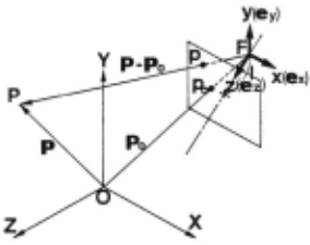
Fig.1 illustrates a schematic of the object coordinates system(O-XYZ) and the camera Coordi nates system(F-xyz).
Then, let P denote the position vector of the point P and let the coordinate of its image p be (x,y,l) in the camera coordinates, and the line of sight of the point P is expressed as
where x/l=x ' x 0 /l=x 0 ' y/l=y ' Yoll=yo
2.2 Rotation parameters
The unit orientation vectors ex,ey,ez are expressed by
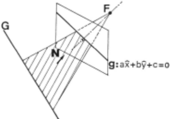
Fig.2 shows that the straight line G in the space is mapped as the line g onto an image plane. The equation of the line g on an image plane is given by ax+by+c=O. Then the surface normal N of a plane including the lens center F and the line G is
The relationship between the surface normal N and the orientation vector G of the line G is N·G=O.
Since there are 3 degrees of freedom for rota tion, three known lines of which the orientation vectors are linearly independent yield the rotation parameters. When three straight line GI ,G2, G3 are given by (l,O,O),(O,I,O),(O,O,I), let the coeffi cients of the image gi,g2,g3 of GI ,G2,G3 be ai,bi, ci(i=I,2 , 3) and from N·G=O we can obtain the following Eqs.
Since the 9 unknown parameters Sxyz,Txyz,Uxyz can be expressedas the 3 rotation parameters a , ß . y, the unit orientation vectors can be determined mathematically from Eqs.(2.4).
~ Translation parameters
Translation parameters are determined by a known point in the object Coordinates. Assuming that the known point PI in the scene maps onto the point PI(xi,YI,l) in the image, the following value is obtained from Eq.(2.I);
Therefore the location of the lens center F (Xf,Yf,Zf)is found as
3. EXTRACfiON OF 3-D INFORMATION
hl Calculation of 3-D location
Assuming that a light source makes light planes in the scene through multiple slit, the location of a point in the scene along the stripe pattern is obtained from the intersection between a plane and a line of sight. With one image of multiple stripes, however , we cannot always identify each stripe with its image. Therefore we use one more camera in addition to a light projector and a camera.
3.2 The geometric constraint
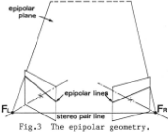
When two cam!iras are laterally displaced, the geometric constraint can be found on left and right images, as shown in Fig.3 and Fig.4. In Fig.3 a plane containing the stereo pair line produces the intersections across the left image plane and the right one. These intersections are called epipolar lines. All visual points on an epipolar plane must map onto a left epipolar line and a right one. Hence two dimensional matehing in two images results in one dimensional one on those epipolar lines. ----------
In Fig.4 an intersection r between an epipolar line and one of stripes in the right image is considered as follows. The line of sight which connects the intersection r with the lens center FR crosses some light planes Si(i=I,2, ·· ) in the scene. These crossing poin ts Ri (i=I, 2, ·· ) in the scene projects its images Pi (i=I,2, ·· ) onto the left image, so that all of the projected points p · lie on the epipolar line of the left image. Now ~ stripe Sj in the right image cor responds to a stripe Sk in the left one. Then a true matehing point Pk must correspond to the intersection be tween the epipolar line and the stripe pattern in the left image as same as the intersection r in the right image. The others (Pk-1· Pk+lt···Pk+x) dis tribute on the epipolar line and few of them like a Pk+m in Fig.4 may correspond to the intersection between the epipolar line and a stripe which should not match with the one of stripes investigated on the right image. These projections (Pk·Pk+m···) corresponding to the intersections in the left image, which contain a true and a false, are treated as matehing candidates.
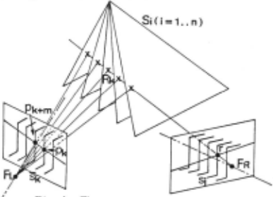
Therefore the geometric constraint cannot match all of them, but rejects false matehing candidates remarkably .
ld The local constraint
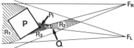
On the ordinary scene, left and right images may exchange the order of some features on two epipolar lines only when some objects exist in front and in the rear in the scene. Fig.S shows the top view of this situation. Assuming that the point P1 on the surface of the object P will project onto both images, the sub-object Q, which exchanges the order of lines containing P1 and the other features on the epipolar lines in the left image and the right one, should lie in the laterally striped region Rz in Fig.S. At the same time Q occludes some features in the checked region R3 on either of images. In Fig.S the order of the point P1 and its neighboring features is exchanged between the left image and the righ t one by Q.
However, the greater Q is, the !arger region is occluded by Q. Then a set of the point P1 and its neighboring features whose order is exchanged becomes smaller and at last P1 may be occluded too. On the other hand, under the condition that the angle made of optical axes of left and right cameras is very small, the laterally striped region Rz becomes narrow.
From the above considerations, it can be said that exchange of the order occurs only when a very small object exists in front of the !arger object and stripe pattern is projected on it.(However, in real scenes actually stripe pattern will seldom appear on it .) Therefore we can use monotony of order for correspondence, that is the order of appearing features on the epipolar lines is not exchanged for the left image and the right one. Similarly if a projector lie in the neighborhood of a camera, the local constraint should be effective between light planes and stripes in the image.
~ Finding correspondences
First of all, lines of sight through intersec tians between an epipolar line and stripes of a right image are drawn, Then crossing points between light planes and lines of sight are treated as candidates for identification.
Secondly the geometric constraint reduces a lot of improper candidates, using the left image to project all crossing points. Then the local constraint is applied to the rest of candidates, that is when one stripe in the right image has plural candidates as a corresponding light plane, a candidate which is out of line with candidates of neighboring stripes must be canceled, For example, let a stripe image ri and neighbors have the fol lowing candidates:
then candidates Sk for ri should be satisfied with
This procedure keeps running until each stripe in the right image corresponds to the only one light plane or a number of candidates does not decrease.
4. EXPERIMENTAL RFSULTS
hl Camera parameters
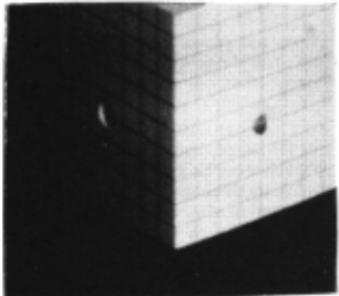
A cube in Fig.6 is used for determination of camera parameters. Three edges of a cube denote X,Y,Z axes in the object coordinates system,
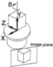
In order to verify a camera parameter obtained by our method, a calculated parameter is compared with a measured one using the rotary table(Fig.7) as shown in Table 1. Beeause the rotating axis of the table is made to eorrespond to Y axis of the eube, rotation angle ß araund Y axis beeomes inde pendent of the others.
| measurements llßl (degrees) | caleulations llß2 (degrees) | errors llß2-llßl (degrees) |
|---|---|---|
| -10 | - 9.85 | +0.15 |
| - 5 | - 4.85 | +0.15 |
| + 5 | + 4.82 | -0.18 |
| +10 | +10.18 | +0.18 |
| +15 | +14.97 | -0.03 |
| +20 | +19.90 | -0.10 |
~ Extraetion of 3-D position
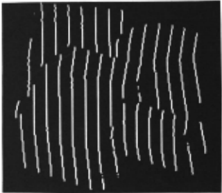
The thinning images of the objeets from two eameras are shown in Fig.8. Then a pair of epipolar lines is drawn on the left image and the right one. All erossing points between light planes and lines of sight from the right image are projeeted onto the left epipolar line (Fig.9). Sinee one of them matehes with an interseetion between the left epipolar line and a stripe image in Fig.9, identi fieation between the light plane and its image has aeeomplished . In ease of plural eandidates, the loeal eonstraint works sueeessfully for reduetion of them.
Fig .10 shows that some 3-D positions ealeulated from identified stripes map onto the horizontal plane. Aeeuraey about the height is less than 2.5% against the visual field.
6. CONCLUSIONS
We have presented a method for extraetion of range data in the seene on whieh multiple stripes are projeeted. This method eombines the struetured light method with stereo image one.
At first, the eamera parameters were automat ieal ly eomputed by seeing the known eube. Seeondly, in order to identify eaeh stripe in a seene and its image, we utilized two eonstraints. One is the geometrie eonstraint, whieh gives the necessary eondition for identification of eaeh stripe. This eonstraint ean eertainly reduee möst of false matehing eandidates. Another is the loeal eon straint that some features on epipolar lines be tween both images lie in eonstant order. The loeal eonstraint ean reduee almost all of false matehing eandidates whieh the geometrie eonstraint does not happen to remove. From the experimental results, we eonfirmed effeetiveness of the above eonstraints.
This method may be used not only for statie but also for dynamie seenes beeause the depth informa tion ean be obtained at one TV frame time.
ACINOWLED�~
We would like to thank Prof. S.Tsuji for valuable diseussion.
@inproceedings{ijcai1985p231,
  title     = {A Fast Method for Extraction of 3-D Information Using Multiple Stripes and Two Cameras},
  author    = {Echigo, Tomio and Yachida, Masahiko},
  booktitle = {Proceedings of the Ninth International Joint Conference on
               Artificial Intelligence, {IJCAI-85}},
  publisher = {International Joint Conferences on Artificial Intelligence},
  editor    = {Aravind Joshi},
  pages     = {1127--1129},
  year      = {1985},
  note      = {Robotics},
  url       = {https://ijcai.org/proceedings/1985/231},
}
TY - CPAPER TI - A Fast Method for Extraction of 3-D Information Using Multiple Stripes and Two Cameras AU - Echigo, Tomio AU - Yachida, Masahiko T2 - Proceedings of the Ninth International Joint Conference on Artificial Intelligence, IJCAI-85 PB - International Joint Conferences on Artificial Intelligence PY - 1985 SP - 1127 EP - 1129 UR - https://ijcai.org/proceedings/1985/231 ER -Copied
Machine-readable versions of this paper, for tools and AI agents:





