
Utilization of a Stripe Pattern for Dynamic Scene Analysis
Proceedings of the Ninth International Joint Conference on Artificial Intelligence. Perception. Pages 895-896.
© 1985 International Joint Conferences on Artificial Intelligence
Abstract
This paper describes a new idea to project a stripe pattern onto a time-varying scene to find moving objects and acquire scene features in the consecutive frames for estimating 3-D motion parameters. At first, a simple temporal difference method detects objects moving against a complex background. A 2(1/2)D representation of moving objects at each frame is then obtained by estimating surface normals from the slopes and intervals of stripes in the image. The 2(1/2)D image is further divided into planar or singly curved surfaces by examining the distribution of the surface normals in the gradient space. Then, the rotational motion parameters of the objects are estimated from changes in the geometry of these surfaces between frames. Determining translational ones is also discussed.
- S.Ullman ,The interpretation of visual motion, MA: M.I.T. Press, 1979.
- M.Asada and S.Tsuji, "Representation of three- dimensional motion in dynamic scenes, " C.V .G.I.P., vol.21, pp.118-144, 1983.
- J.-Q.Fang ancl T.S.Huang, "Same experiments on estimating the 3-D motion parameters of a rigid body from two consecutive image frames," IEEE Trans. Pattern Anal. Machine Intell., vol.PAMI-6, pp . 545- 554, 1984.
- M.Ohshima and Y.Shirai, "A scene description method using three-dimensional information," Pattern Recognition, vol.ll, pp.9-17, 1979.
- M.Mericlel, J .Lund gram and T.Sorensen, "Cascade, an algorithm to reduce the effect of mixed pixels," Proc. of CVPR-83, pp.53-58, 1983.
References were extracted automatically from the PDF and may contain errors.
Full text extracted automatically from the PDF; figures, tables and equations may differ. The PDF is the version of record.
1. INTRODUCTION
Determining of 3-D motion parameters in a time varying scene is a current problern in computer vi sion. Interesting theories have been presented to estimate 3-D motion of objects from a sequence of images taken by a camera [ 1-3]. They, assuming the rigidity of objects, analyze changes in geometry of object's images in the consecutive frames to obtain 3-D motion cues. The results of applying these theories to real scenes, however, are very sensitive to noise and unsatisfactory in most cases. We, therefore, need a reliable method to obtain scene features from each frame in the image sequence.
A method useful for acquiring 3-D information is to project the structured light to the scene. Since the time for scanning a slit light [4] is too long
IITILIZATION OF A SlRIPE PATTERN
FCR DYNAMIC SCENE ANALYSIS
Minoru Asada and Saburo Tsuji
Department of Control Engineering
Osaka University
Toyonaka, Osaka 560, Japan
for the dynamic scene analysis, we use a dense stripe pattern as the structured light. One advan tage of this method isthat a simple temporal dif ference method can easily detect objects moving a gainst a very complex background, saving a consider able computing time.
If the stripe is dense, finding of correspondence between each stripe pattern in image and light stripes in scene is difficult, especially when the scene contains many concave objects or discontinuous boundaries. As a result, our method cannot provide with the range information at each image point. Surface normals as important scene features, howev er, are available at a number of points distributed densely in the image.
The image acquisition system is arranged such that all light stripes in scene are almost parallel and the projection from scene to image is Orthographie. Thus, we can obtain a 2(1/2)D representation of the moving objects at each frame by estimating the sur face normals from the slopes and intervals of the stripe.
The 2(1/2)D image is further segmented into planar or singly curved surfaces by finding and examining clusters of the surface normals mapped onto the gradient space. Although the estimate of each sur face normal is somewhat inaccurate, we can obtain much better estimates of geometrical parameters of these surfaces by utilizing the continui ty in each surface. The rotational movements of the objects are determined from changes in these parameters between consecutive frames. The estimation of the transla tional components from these changes is difficult, however, we could utilize cues to get the range information as discussed in the final chapter.
(b) The 5th frame.
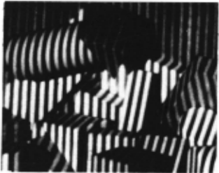
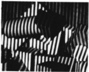
Fig.l Examples of input images.
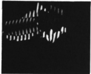
Fig.2 The difference picture between (a) and (b) in Fig.l.
2. HETHODS
We apply the method to a real scene shown in Fig.l. Input images consist of 256*240 pixels, 8bitslpixel. Many blocks are stacked up, and a cylinder with a wedge is moving above them. It seems difficult to extract moving objects because of complexity of backgr ound.
2.1 Extraction of Hoving Objects
The first step of dynamic scene analysis is to separate non-stationary portions from the stationary background. In our case, a differeuce picture of gray values between two consecutive frames shows mos t parts of moving objects, because the stripe pattern on an object surface is changed in its position, slope or intervals in image by the object motion in most cases.
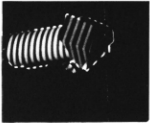
Fig .2 shows a difference picture of gray values between the 2nd and the 5th frames, which displays the absolute value of difference. We can see the region covers almost whole parts of moving objects while, by ordinary lighting, overlapping part of moving objects in those frawes will not be detected. In order to extract the moving object at the 5th frame, we take one more difference picture between the 5th and the 8th frame, and take the AND picture of two difference pictures, then the region of mov ing object at the 5th frame is left (frame interval is arbitrarily chosen). Small holes and cracks are eliminated by region growing. As a result, the mov ing object at the 5th frame is extracted (See Fig . 3) .
2.2 Determination of Surface Orientation
The surface orientation is determined locally from the slope and intervals of each stripe in image.
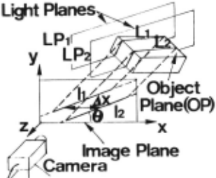
Fig.4 shows the geometrical relations among light planes and an object plane in the camera-centered coordinate system. We define the equations of two light planes 1P1 and 1P2 parallel to each other and of an object plane OP on which a stripe pattern is projected, as
and
where Ps and Qs are parameters which represent the direction of light source in a projector and (Po,Qo) is the surface orientation. The object plane OP and the light plane 1P1 (1P2) intersect in a line 11 (12). The projection of two lines 11 and 12 onto the image plane (the x-y plane) are defined as 11 and 12, respectively. The slope of these lines (tan6) and the distance between them (ax) in the x-direc tion are easily measured in image since we assume the orthographic projection.
The geometrical relation among these variables leads to the following equations,
and,
That is, the surface orientation (Po,Qo) of a point on an object is calculated locally from the slope (tan6) and intervals (f:"x) of the stripe in the
image.
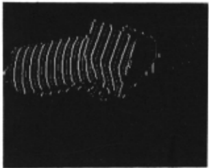
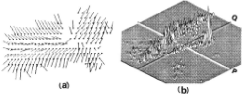
In order to obtain the surface normal, the system detects edge segments from the striped image of moving objects (See Fig.5). The location of edge point is estimated in a sub-pixel order by using the Linear Mixing Model [5] of intensity araund the boundary between dark and bright regions to reduce the effect of digitizing error. The system fits a line segment to seven successive edge points. Those segments whose fitting error exceeds a threshold are discarded as discontinuous boundaries. From the slope and intervals of these line segments, we can calculate the surface orientations. Fig.6 (a) shows sampled surface normals on the moving objects ob tained at the 5th frame. A histogram of these surface normals in the gradient space are shown in Fig.6 (b).
2.3 Hotion Analysis
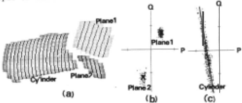
Let us consider how we can utilize the 2(1/2)D images to estimate the 3-D motion parameters. At first, we map the obtained surface normals onto the gradient space in order to segment the 2(1/2)D image into planar or singly curved surfaces (see Fig.6 (b)). Surface normals on a plane make a cluster in the gradient space. By mapping them from the gra dient space into the 2(1/2)D image reversely, we obtain the planar region. Its orientation is pre cisely estimated by calculating again with Ionger line segments and wider intervals.
Also, surface normals on a singly curved surface, for example, a cylindrical surface make a line-like cluster in the gradient space. The line parameters obtained by fitting a line to the cluster gives u.3 the orientation of generating line of the cylindri cal surface. Its orientation makes the surface pa rameters more precise.
Since the lower surface of wedge is parallel to the generating line of the cylindrical surface, the cluster corresponding to it is merged in a line-like cluster (See Fig.6 (b)). Therefore, we cannot detect the lower surface of wedge in the gradient space at first. The line-like cluster, however, is segmented into two surfaces by examining the surface continui ty on the 2(1/2)D image. Fig.7 shows the results of the segmen ta tion.
Since each 2(1/2)D image is segmented into planar or singly curved surfaces, it is easy to find corre spondence of these surfaces between consecutive frames. Table 1 indicates the angles between the surfaces at the 4th and the 5th frames. The orienta tion of cylindrical surface is represented as the direction of generating line. Little changes of them between frames shows the rigidity of object. Assum ing it, we determine the accurate rotation parame ters from the precisely obtained surface properties at each frame.
3. DISGUSSIONS
We have determined the rotational movement of object from the changes of surface geometry between frames. They, however, can provide us with little informa tion on the translational movement. Thus, let us consider how we can get the range information from such images as shown in Fig.1 to determine the translation.
Shadow parts give us a very important cue to ex tract the depth information. Utilizing the projec tions of light lines onto the image plane, which are equivalent to the epipolar line in stereo vision, we can label each stripe in image between two surfaces which are discontinuous as shown in Fig.8 . This figure displays the upper surface of the wedge and its shadow on the back wall in Fig.1 (b). Then, the relative distance between them is obtained from the equations of light stripes in scene.
If two surfaces are continuous , stripe edges in image are connected across their boundary. There fore, we hypothesize that the range is continuous between two surfaces where stripe edges in image are connected, although it is not always true .
Most parts of the image would be interpreted by propagating the consistent labeling of stripes with the shadow information and the cue of surface conti nuity. There would remain several candidates of interpretation for unknown portion of the image.
@inproceedings{ijcai1985p179,
  title     = {Utilization of a Stripe Pattern for Dynamic Scene Analysis},
  author    = {Asada, Minoru and Tsuji, Saburo},
  booktitle = {Proceedings of the Ninth International Joint Conference on
               Artificial Intelligence, {IJCAI-85}},
  publisher = {International Joint Conferences on Artificial Intelligence},
  editor    = {Aravind Joshi},
  pages     = {895--896},
  year      = {1985},
  note      = {Perception},
  url       = {https://ijcai.org/proceedings/1985/179},
}
TY - CPAPER TI - Utilization of a Stripe Pattern for Dynamic Scene Analysis AU - Asada, Minoru AU - Tsuji, Saburo T2 - Proceedings of the Ninth International Joint Conference on Artificial Intelligence, IJCAI-85 PB - International Joint Conferences on Artificial Intelligence PY - 1985 SP - 895 EP - 896 UR - https://ijcai.org/proceedings/1985/179 ER -Copied
Machine-readable versions of this paper, for tools and AI agents:





