
Program Transtormations for VLSI
Proceedings of the Eighth International Joint Conference on Artificial Intelligence. Automatic Programming. Pages 40-42.
© 1983 International Joint Conferences on Artificial Intelligence
Abstract
VLSI design can be modelled as a series of transformations leading from a high -level formal specification to a concrete implementation . Automating such transformations offers a way to improve the reliability of the design process while reducing its cost. This paper addresses the portion of the design process that converts abstract algorithms into functional-level circuits (collections of primitive computational elements and their interconnections) . By defining an isomorphism between such circuits and a highly restricted subset of programs. we can apply source-to-source program transformation methodology to the problem of mapping algorithms into circuits. This methodology has been implemented in a system that has successfully rederived much of the design of a published VLSI graphics display processor.
- Balzer, R., N. Goldman . and D. Wile, "On the transformational implementation approach to programming," in Pro c eedings of the 2nd Internationa l Co nferenc e on Software Eng ineering , pp . 337•343, IEEE , 1976.
- Fuchs & Poulton 81
- Fuchs, H., and Poulton , J. , "Pixel-Planes: a VLSI -oriented design for a raster graphics engine," VLSI Design , (Third Quarter) , 1981 , 20•28.
- Lam & Most ow 83]
- Lam , M., and Mostow. J. , " A transformational model of VLSI systolic design ," in IFIP 6th International Symposium on Compu ter Hardware Descriptio n La nguages and their Applications . Carnegie-Mellon University. May 1983. [London & Feather 82] London .
- P.E. & Feather, M.S .. "Implementing specification freedoms," Sc ienc e of Compu ter Programming , (2) , 1982, 91•131 .
- Mostow & Balzer83] Mostow, J ., and Balzer, B., " A Program• Transformation Approach to VLSI design ," in Proceedi ngs of the 1982 Works hop on Software Eng ineering and VL SI, IEEE, 1983.
- Teitelman , W. , lnterlisp Referenc e Manual , Xerox Palo Alto Research Center, 1978.
References were extracted automatically from the PDF and may contain errors.
Full text extracted automatically from the PDF; figures, tables and equations may differ. The PDF is the version of record.
1. Introduction
Continuing advances in VLSI fabrication technology are making the development of correct, efficient VLSI designs a crucial bottleneck in the same way that falling hardware costs have exposed a similar bottleneck in software development. Our research group at lSI has been attacking the latter problem for several years [Balzer et al 76] . We believe that the similar character of VLSI design makes it amenable to the same transformational design paradigm we have been using for software [Mostow & Balzer 83].
We model the VLSI design process as developing a behavioral specification and then converting it into a circuit by applying a series of transformations. Alternative transformations at each step correspond to alternative design decisions.
This paper starts at the point where a specification has been developed and mapped down to the algorithm level, and shows how transformations can be used to take it from there to the functional-circuit level.
2. A Program Transformation Model of Design
The transformational approach requires a way to represent the initial algorithm, the resulting functional -level circuit consisting of a collection of hardware cells and their interconnections, and the intermediate design states in which some but not all of the decisions have been made.
To simplify the representation problem, we consider only synchronous circuits. Specifically, we assume a two-phase ports. Thus an exception to the prohibition on concurrent calls is made in the case of arbitrator-like modules that are called simultaneously by several callers through distinct input ports. A special case is an output-only module such as a time· of-day server. Another exception is pipelining: a multi·stage module can process several overlapping calls, provided none of them tries to use the same data line at the same time.
This research was supported by DARPA Contract MDA-903-81 ·C-0335. The views and conclusions contained in this document are those of the authors and should ·not be interpreted as representing the official policies, either expressed or implied, of the Defense Advanced Research Projects Agency or the US Government. I am grateful for intl:llectual contributions by Monica Lam, comments by lSI colleagues. and improvements by Don Cohen.
Explicit communication: No global variables are allowed, and a procedure body may refer only to its input arguments and its own variables. This is because in VLSI , accessing a variable requires a physically wired path to the place where it is stored. To model these paths, we require that non·local values be explicitly passed as arguments or returned as procedure results.
Explicit control: A procedure body must be a finite state machine that executes one transition per clock cycle and stores all its state in its local variables; all functions computed in a single cycle must be combinational. Functions that satisfy this restriction have a straightforward hardware analog. More complex functions must be implemented by breaking them down into a series of single-cycle computations.
3. Some Transformations
We have developed a collection of transformations for mapping ordinary programs into the restricted form, and have implemented several of them using lnterlisp's Pattern Match Compiler [Teitel man 78] . The transformations can be classified according to the type of decisions they make: allocation, modularization, or control. -We now present some example transformations of each type and then show how they apply to the Pixel Planes [Fuchs & Poulton 81] graphics display chip.
3.1. Allocation
To implement an algorithm in hardware, every operation must be assigned both a component and a time. A repeated operation may be distributed in time and/or space. For example, a multiplication inside a loop may be implemented by re-using a single multiplier, or by replicating the multiplier and executing the loop body simultaneously for all values of the loop index in parallel.
Suppose we wish to implement a loop of the form
for each xES do <body>;In the sequential re-use allocation scheme, we build a module M that inputs x and performs the loop body, and then invoke this module for each x in sequence:
procedure M(x) ; <body>; end M; Driver: for each xES in sequence do M( x) ; An alternative is to build one module for each element x 1 , ... , xn of S, and invoke all the modules in parallel : procedure M[iEl .. n](x); <body>; end M; Driver:
This allocation scheme is called parallel replication . It requires that executing <body> for one element x does not affect the result of executing it for another element. Note that in the expression M(i](x.). the index i distinguishes among modules in the array, while the argument x. represents a value passed to an input port in module M(i] . One' might choose to eliminate this port by hardwiring the value xi into the module.
A third scheme, pipelining , is discussed elsewhere [Lam & Mostow 83] , but further work is required to fit it into the program representation used here.
3.2. Partitioning into Modules
An algorithm can refer to the value of a variable simply by naming it. but in VLSI accessing a variable requires wiring a connection to the point of use from wherever the variable is stored. To implement an algorithm in hardware, the communication paths between components must be made expl icit.
We have implemented an interactive procedure, called MAKEARGSEXPLICIT, for doing this. Suppose we have decided to implement in hardware _11,n algorithm containing a nested function call f(g(x)) , where the variable x is defined external to the function call . Some module F will compute the expression f(g(x)) . The partitioning question (in its simplest form) is, will module F input x and compute g(x) itself, or will the value ot g(x) be computed externally and supplied as input? In gerntral , the functions may take multiple arguments and the function calls in the algorithm may be mbre deeply nested, but this is the basic idea. MAKEARGSEXPLICIT systematically traverses an expression being implemented in a module, asking the user whether each sub expression that uses data external to the module should be computed inside or outside the module. Based on this information, it determines the input ports for the module.
Such decisions may appear unimportant: after all, g(x) must be computed somewhere, so what does it matter how the computation is partitioned into modules? The answer is that different decisions can in fact lead to very different designs. For example. if f(g(x) , y) is computed by many F·cells (one for each value of y) , then computing g(x) externally enables its value to be computed once and broadcast. Whether this is better than broadcasting x and computing g(x) inside every cell can depend on such factors as the relative data widths of x and g(x). and the relative area costs of computing g versus transferring data.
3.3. Control
Control transformations map algorithm-level control constructs, such as iteration and complex conditionals, into forms that correspond directly to hardware constructs, or move them out of module definitions into the enclosing driver. By doing this repeatedly, problematical constructs can be translated away or extracted into the driver for the whole chip, leaving a finite·state machine description of the chip itself. The chip driver is simply a description of how to use the chip, so it is allowed to contain iterative constructs. For illustration, we present two transformations used in the Pixel Planes example.
The first transformation implements conditionals of the form
The transformation implements this conditional by introducing a one· bit Enable register, initialized to True, and using it to compute the condition incrementally. If afterwards the register is still enabled, the <body> is performed:
begin own boolean En ab 1 e; Enable .. T; foreach xES do Enable .. Enable A P(x) ; if Enable then <body>; end;The transformed program is closer to the hardware level because the complex condition in the conditional has been replaced with a simple flag. This can be implemented by gating the Enable register with the evoke signal for <body>. For example, if <body> is a register assignment, Enable would be gated into the register's write-enable line.
One may object to this implementation on the grounds of inefficiency: although the Enable register may be disabled early on, P(x) will still be computed for every element of the set S. The answer to this objection in the Pixel Planes example is that the transformation is used to implement a conditional performed at every pixel in parallel. By iterating unconditionally, the pixels can share control signals broadcast from a common driver. This illustrates how a program ill-suited to execution on an ordinary sequential processor may represent a hardware-efficient implementation.
A second transformation helps implement begin ... end blocks. Consider a procedure whose body is a begin .. . end block:
procedure F(x): begin <stmt 1 >: .. . ; <stmtn> : end; end F: Driver: F( <expr>) :The transformation extracts the begin .. . end block into the driver for F by converting the body of F into a case statement and adding a control input to module F that tells it which action to select. Such a case statement can readily be implemented in hardware by combinational logic that decodes the control input and invokes the selected action. The driver is changed into a series of calls to F, one for each statement in the begin ... end block:
procedure F(ctrl. x); case ct rl of end: end F; Driver: begin case 1 : <stmt 1 >: F(case 1 , <expr>): ... ; F(casen, <expr>): end:The program that applies this transformation identifies which calls actually use the value of the input x. In those that do not, the pseudo-argument " ·· ·· is passed instead. This facilitates input· line-sharing optimizations (not yet implemented) . For example, ifF
has several inputs. but only one is used at a time, they can share the same input line.
The above transformation implements external control: an external control input tells the module what to do for each call. An alternative is to introduce an internal state register and update it after each call , returning a control signal to notify the caller when the block is completed.
4. The Pixel Planes Example
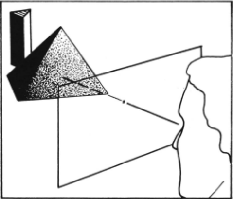
We now show how transformations like those described above can be used to re-derive the design of the Pixel Planes graphics display processor [Fuchs & Poulton 81]. As Figure 4-1 shows, successive scenes consisting of polyhedral objects with colored faces are to be displayed, with hidden surfaces eliminated and the shading of each face interpolated from the colors of its vertices. A pre-processor segments the objects into triangular faces and transforms them into viewing coordinates. The position and color of every vertex are input to the Pixel Planes chip, which must compute what color to paint each pixel on the display screen . The high-level specification can be expressed informally as " for each scene, color each pixel the shaded color of the nearest face. "
The algorithm can be expressed as: for each sEScenes do · foreach pEPixels do begin minZ ~ 00; for each tEFaces do if forall eEEdges{t) A9 xp/\+ BAeYp + C9 > then begin txp + Btyp + Ct < minZ end; minZ ~ Atxp + Btyp + Ct; Display(p] ~ A 5 xP + B 5 yP + C 5 : end:How this algorithm works is irrelevant here; we are interested only in its syntactic form. First, notice that 'it contains several planar expressions of the form AxP + ByP + C. Second, notice the presence of the begin ... end blocks and the complex conditional statement "if forall .. . /\ ... then ... . "
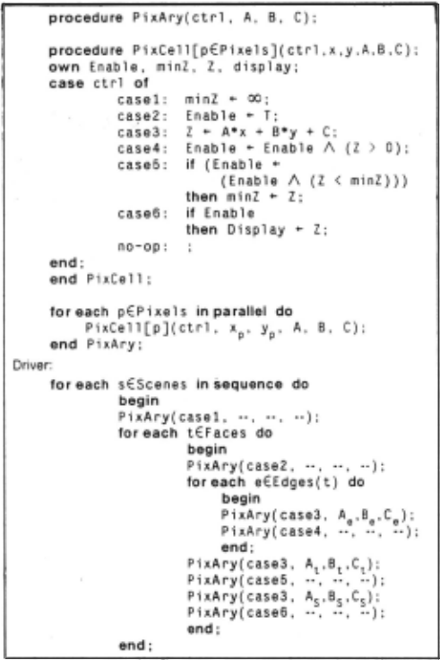
By applying transformations such as those described in the previous sections, we obtain the program shown in Figure 4·2. This program reflects the following design decisions (some of which are revised by subsequent optimizations):
1. Allocation:
- Use a replicated PixCell[p] to compute pixel color in parallel for each pixel p.
- -Multiplex hardware for Axp + ByP + C.
2. Partitioning :
- ·Compute AxP + ByP + C inside PixCell[p] .
- Import planar coefficients A, B. C from outside PixCell[p].
3. Control:
- Implement the complex conditional using an Enable register.
- Use an external control line to select the action performed by PixCell[p].
This would be a poor decision ~ it were allowed to stand. since using two multipliers for every pixel would be very costly in area. It alsc pretends that the muniplication is performed in a single clock cycle. In the actual design. the products Ax (and By ) are computed externally and broadcast bit-serially to all pixels with t~e same vCiue of x (or y ). These refinements are omitted above for simplicity. P P
At this stage in the design process, PixAry represents a pixel array that inputs a control code and the coefficients A, B, and C, and broadcasts them to all the PixCells, as well as sending each PixCell its x and y coordinates. The control code tells each PixCell what do to in a given clock cycle; note that case3 is the computation of a planar combination. The nested assignment in caseS specifies that the value of Enable 1\ (Z < minZ) is both stored into the Enable register and used as a condition for whether to update the minZ register. The driver tells what sequence of control signals and data to send to PixAry: note that case3, for computing planar combinations. is used several times.
A key point here is that the transformations used to model these decisions are general, even though the decision to select them instead of alternative transformations depends on understanding their consequences at lower levels of design.
5. Conclusion
We have modelled part of the VLSI design process as a series of transformations leading from a specification to a design. Letting the machine apply these transformations should decouple the human selection of design alternatives from the mechanical manipulations required to carry them out, reducing errors and freeing the designer to explore a wider range of design alternatives.
VLSI design traverses many levels, going from specificat ion to algorithm to functional -level circuit to layout. The problems of developing a formal specification and mapping it into a compilable algorithm are receiving attention at lSI [London & Feather 82] and elsewhere. We have focussed in this paper on a narrow slice of the design problem: getting from algorithm to functional-level circuit. Practical application of this work will require a "silicon compiler" ·like mechanism for completing the design process.
Past work in automatic programming has emphasized the synthesis of sequential programs. With the VLSI revolution upon us. program synthesis techniques should be applied to the problem of how to exploit the parallelism offered by this new technology.
@inproceedings{ijcai1983p9,
  title     = {Program Transtormations for VLSI},
  author    = {Mostow, Jack},
  booktitle = {Proceedings of the Eighth International Joint Conference on
               Artificial Intelligence, {IJCAI-83}},
  publisher = {International Joint Conferences on Artificial Intelligence},
  editor    = {Alan Bundy},
  pages     = {40--42},
  year      = {1983},
  note      = {Automatic Programming},
  url       = {https://ijcai.org/proceedings/1983/9},
}
TY - CPAPER TI - Program Transtormations for VLSI AU - Mostow, Jack T2 - Proceedings of the Eighth International Joint Conference on Artificial Intelligence, IJCAI-83 PB - International Joint Conferences on Artificial Intelligence PY - 1983 SP - 40 EP - 42 UR - https://ijcai.org/proceedings/1983/9 ER -Copied
Machine-readable versions of this paper, for tools and AI agents:





