
Model-Based Three Dimensional Interpretations of Two Dimensional Images
Proceedings of the Seventh International Joint Conference on Artificial Intelligence. Vision: 3-d. Pages 619-623.
© 1981 International Joint Conferences on Artificial Intelligence
Abstract
ACRONYM io a comprehenoive domain independent modelhued syatem for vioion and manipulation related taakl. Many of ito aub-modulea and representation• have been deacribed elsewhere. Here the derintion and use of invariant• for image feature prediction io deacribed . We deacribe how predictions of image featurea and their relation• are made and how instructions are generated which tell the interpretation algorithms how to make use of image feature meuurmenh to derive three dimensional aises and otructural and opatial conotrainta on the original three-dimenaional models. Some preliminary examples of ACRONYM'• interpretation• of aerial images are shown.
- Baker, H. Harlyn; Edge Baaed Stereo Correlation, Proceedinp ARPA Image UnderatanJing Workahop, College Park, MD, April 1980, 16S.175.
- Binford, Thomaa 0 .; Computer Integrated A111embly Sy1tem1, Proceedings NSF Grantee• Conference on Industrial Automation, Cornell Univ .; Sep. 1979.
- Bledaoe, W. W.; The Sup-In! Method in Presburger Aritbmetic, Memo ATP-18, Dept.• of Math. and Comp. Sci., UniYenity of Texu at Auatin, Auatin, Texu, Dec. 1974.
- Bobrow, Daniel G. and Terry Winograd; An Overview of KRL, a Knowledge Representation Language, Cognitive Science 1, 1977, 3-46.
- Brooka, Rodney A.; Goal-Directed Edge Linking and Ribboa Finding, Proceedings ARPA Image Understanding Workahop, Menlo Park, April 1979, 72-76.
- Brooko, Rodney A.; Symbolic Reuoning Among 3-D Models and 2-D Images, AI Journal, to appear.
- Brooko, Rodney A., Ruasell Greiner and Thomas 0 . Binford; The ACRONYM Model-Bued Vision System, Proceeding• IJCAI-6, Tokyo, August 1979, 105-113.
- Brooks, Rodney A. and Thomas 0 . Binford; Repreaenting and Reaaoning About Partially Specified Scenes, Proceeding• ARPA Image Understanding Workshop, College Park, MD, April 1980, 95-103.
- Brooks, Rodney A. and Thomas 0 . Binford; Interpretive Viaion and Restriction Graphs, Proceedings of the Firat Annual National Conference on Artificallntelligence, Stanford, Auguat 1980, 21-27. 623
- Nentia, Ramakant and K. Rameah Babu; Linear Fea' &ure Extraction and Deacription, Computer Graphic• and !mace Proce11in1 13, 1980, 257-269.
- Shoetak, Robert E.; On the SUP-INF Method for ProYi.q Preabur1er Formulu, JACM 24, 1977, 52~543 .
- Soroka, Barry 1.; Debuging Manipulator Program• with a Simulator, Autofact Weat Conference, Society of Manufacturin& Engineera, Anaheim, Nov. 1980.
References were extracted automatically from the PDF and may contain errors.
Full text extracted automatically from the PDF; figures, tables and equations may differ. The PDF is the version of record.
1. lntrocluction
At the previoua IJCAI we reported IT] on the deaign and d& velopment of a model-hued vioion oyatem called ACRONYM, which could indentify instances of modeled objecta in imagea. Since then the acope of AcRONYM baa been increaaed to include extraction of three dimenaional information from imagea (including monocular imageo} II], reasoning about how to grasp objecta (Binford 12]}, and real time oimula tion of multiple manipulator work atationa for purpose· of oll'-line pro gramming and the deoign and analyoia of new manipulaton (Soroka 112]).
To support these devlopmenta we have added a cla11 and oub clasa relation representation acheme to the geometric modeling oyotem (It], IG]}. This is baaed on the uae of symbolic algebraic constraint.. In aupport of thia a conatraint manipulation systems which includeo a par tial decioion procedure on consiatency of aeta of non-linear inequalities was formulated and implemented IGJ. A geometric reasoning oyotem which can deal with underconatrained spatial relatione was developped 18]. A new matcher which could manipulate the constraint ayatemo was built for interpretation 19] .' All of tbeae aystems were implemented in a mixture of MACLISI' and a new rule ayatem built for the purpoae.
We have thus moved from a purely geometric representation and qualitative geometric reasoning ayatem to a aystem with a com bined algebraic and geometric representation and a geometric reaaon ing ayatcm which can make precise deductions about partially specified situations. The geometric and algebraic aspecta of the repreaentation complement each other during interpretation.
In this paper we deal with the techniques developed for image feature and feature- relation prediction, and then give aome lint ex amples (February 1981) of the performance of the new incarnation of ·ACttoNYM on some images. The low level processes we currently use provide either little or noisy data. Nevertheless AcHONYM makeo strong and accurate deductions about the objects appearing in the images. We expect even better performance when more accurate low level descriptive processes become available.
This work was supported by the Defense Advanced Research Project. Agency under contract MDA903-80-C- 0102, by the National Science Foundation under contract DAR78- 1S914 and by a grant from the ALCOA corporation.
2. Pwtietjon
In the ACRONYM system generic object clasaeo and 1peei6c objecta are repreaented by volumetric models baoed on generalised coneo alon1 with a partial order on oeta of non-linear algebraic in equalitiel relatin1 model parameters. Image feature. and relation· between them which are invariant over variation· in the model· and camera parameters are identified by a geometric reaaoning ·Y·tem. Such prediction· are combined first to give guidance to low level image description proces-, then to provide coarae filters on image feature· which are to be matched to local predictions. Prediction· alao contain instructions on how to use noisy measurements from identified image features to construct algebraic constraints on the original three dimen sional models. Local matches are combined subject both to conoiotently meeting predicted image feature relation·, and the formation of conU. tent aet1 of algebraic con1trainta derived from the image. The reoult ia a three dimenoional interpretation of the image.
Thio oection deacribeo oome of the invariant. that are identified by the reaooning ·ystem, and give· example. of how the back con straint. are aet up giving three dimensional information about the in stances of the models which appear in image1.
2.1 Conokljpy
To illuminate the discussion in oucceeding oub-oections we briefly deacribe the u1e1 and capabilities of AGRONYM'I con·traint mechanism and the allowed atructure of constraints themoelveo.
AcRONYM'· three-dimensional models are represented by unit· and a/ots (e.g. Bobrow and Winograd 1-t}). Any olot which admita numeric Iii/era alao admit. quanti.tlers (predeclared variable name~) and expre11ion1 over quanti! en using the operators +, -, X, f and ..;.
Con1trainta can be put on quantifiers. They take the form of inequalities between expreuions as defined above, along with the possibility of including max and min (on the left and rilbt of $, respectively). Equality can be encoded as two inequalities. For in1tance suppose a cylinder is repreaented as a generalised cone whooe 1traipt apine baa ita length defined by the quantifier CYL_LENGTH and whoae crou section is a circle with radiua CYL_RADIUS. Then the claso of all cylinders of volume 5 (in aome units} can be repreoented by the two constraint.:
- 5 2:: CYL_LENGTH X CYL_RADIUS X CYL_RADIUS X "
- 5 $ CYL_LENGTH X CYL_RADIUS X CYL_RADIUS X "
The Ac ttoNYM constraint manipulation sy1tem (eMs}, described in detail in IGJ, operates on seta of constrainto. A oet of con straints (implicitly conjunctive) defines a subset of n- dimenaionalapaee for which all constraints are true (where n ia the number of quantifien mentioned in the constraint oet). This is called the satisfying oet, and is empty if the constraint.· are inconaiatent. The CMS is used for three tasks related to this conatraint set.
- Given a set of constraints partially decide whether their oatiafying set is empty . The outcomes are "empty" or "I don't know".
- Find numeric (or ±oo) upper and lower bound· on an ezpreuion in quantitera OYer the utiafyin& ~et of a conatraint ~et. Thia u procedure~ called SUP and INf.
- (A pnerali1ation of 2.) For and ezpreaaion E and a ~et of quantiflen V find ezpreuiona L and H in V auch that L ::; E ::; H identically OYer the utilfyin& ~et of the conatrr.int ~et.
- In 2 and 3 the ezpreaaiona bein& bounded can include triaonometric function· aucb u lin, co· and arcain. Tbe CMS we han implemented in ACRONYM i· a non-linear aeneralisation of the linear SUP- INF method de~eribed by Bled10e 13), and Sb01talc Ill). It behal'el identically to that deiCribed by the latter for purely linear letl of COJio atraintl and linear expreuiona. In addition it can often produce &Dod bound· (numeric and ezpreuiona) on hi&bly non-linear expre~liona in the preaence of many non-linear conatraintl.
2.2 Shape predldlaa
We predict lbapea u ribbon· (the two dimenlional anaJocue or three dimenaional aeneraliaed cone·) and ellipeu. Tbeae are al10 the feature· which are found by tbe low lenl de~eriptin procea1 we are temporarily Ulinl in ACRONYM.
Ribbon· are a aood way or de~eribing tbe imacea aenerated by cenerali1ed conea. Conaider a ribbon wbicb correaponda to tbe imace or tbe awept aurface or a generalised cone. For straight apines, the projec tion of the cone spine into tbe image would cloaely correapond to the apine or the ribbon. Thus a good approximation to the ob~e"ed an&Je between tbe ·pines or two generalised cone· is tbe an&Je between the spine· or tbe two ribbon· in the imace correspondin& to their swept aur faeea. We do not have a quantitative theory or tbeae correapondencea. Ellip1e1 are a &ood way or de~eribing tbe lbapes generated by the end· or ceneraliaed conea. Tbe perspective projection· or end· or cone· with circular croa .... ~ectiona are exactly ellip-.
Shape prediction involvea decidin& what sbapea will be vilible, predicting ranae· for abape parameten (to be uled u a coarae filter dur in& interpretation and aloo to auide tbe low level deiCriptive proceae~) and deriving inatructiona about bow to locally innrt the perapectin tranaform and hence use imace meuurementl to pnerate conltraintl on the ori&inal three dimenlional models.
To predict the abape1 pnerated by a ain&Je pnerali1ed cone, we do not explicitly predict all pouible qualitatively dilferent view pointl. Rather we predict what lbapea may appear in the image, and uaociate with them method· to compute conatraintl on the model that are implied by their individual appearance in an tbe imace. For ez ample, identification or the imace or tbe awept aurraee or a ri&bt circular cone conatraina tbe relative orientation of the cylinder to tbe camera (we call theae back constraint·). Identification or an end race or the cylinder prOYidea a dilferent set or conatraintl. Jr both the swept aur race and an end race are identified then both ~etl or conatraintl apply. We alao predict apecilic relation· between lbapea that wiU be true if they are both ob~e"ed correctly. For more complex cone·, the payolr is even greater for predicting individual lbapea rather than exbauative analysi· or which abapea can appear toaetber.
At other timea during prediction invariant cuea of ob~euration are noticed. For inatance it may be noticed tbat one cone abutl another 10 that ita end race will never be viaible. The consequence· of auch realisations are propacated through the prediction·.
Prediction or abapea proceed· in live pbuea. Fint, aU tbe contours on a pnerali1ed cone wbicb could give rise to imace abape1 are indentilied by a ~et or apecial purpo~ rulea. These include occluding contoun and contoun due purely to internal cone facea. Tbua for inatance a right square cylinder will generate contoun for the end faces, the awept facea, and contouu generated by the awept edce· at diagonally vertices or the square crou aection. The contoun are generated independently of camera orientation, and in term· or object dimenaiona rather than imace quantitiea.
Second, the orientation or the generalised cone relative to the camera (tbi1 i1 done by tbe geometric reuoning syatem, aee 18), II)) il then examined to decide which contours wiU be visible and bow their imace lbapea wiU be diatorted OYer tbe range of variation· in the model parameter· which appear in the orientation ezpreaaiona:
Tbe third phase predicta relation· between contoun of a ain&Je generalised cone (see aection 2.3).
Fourth, tbe actual lbape1 are then predicted. Tbe expected valuea for abape parameters in tbe image are estimated as clQJed inter val· (- below).
FinaUy tbe back conatrainta which will be inatantiated durin& interpretation are conatructed.
2.2.1 Back conatraintl
Suppoae that we wiab to predict tbe length of an obaervable feature which is generated by aometbing of length I lying in a plane parallel to the camera image plane, at distance d from the camera. Furthermore suppose tbe camera baa a focal ratio of f. Then the meuured length or tbe obaerved feature is given by p = (I x /)/d. Any or all of I, f and d may be expresaions in quantifiers, rather than numben. Uaing the CMS we can obtain bounds on tbe above expreuion for imace feature length, giving that it will lie in aome range P = IP1.P~J where 1'1 and Ph are either numben or ± oo. For more complex geometriea the expre11ion for p will be more complex, but the method ia the aame (trigonometric function· are uaually involved).
Now, given an image feature, wbicb is hypothesised to cor reapond to the prediction we have to decide whether it acceptable on the buia of ita parameters. The low level de~eriptive proce1se1 are noily and provide an error interval, rather than an exact meuurement for image parameteu. Suppose the interval ia M=lm1, mh) for a feature parameter predicted with expre11ion p. Then the parameter i1 accept able it P n M ia non~mpty. Tbia ia tbe coane filtering used during initial bypotheaia or image feature to feature prediction matchel.
But note also that it muat be true that the true value or p for the particular inatance of the model wbicb ia being imaged muat lie in the range M . Tbua we can add the conatraintl:
to tbe inatance of tbe model being bypotheaised, where I, f and d are numben or expre11ion· in quantifiera.
2.2.2 Triconometri~ bult conatraintl
When the expreaaion p involve· trigonometric function· the above method of generating back conatrainta wiU not work. It would pnerate conatrainh involving trogonmetric function·, which our CMS can not handle.
One approach to tbia problem i· to bound expreaaion p abOYe and below by expreuiona involving no quantifieu contained in arcu menta to trigonometric functione, and then uae tbeae exprealion1 in letting up the back conatrainh. Thi· baa tbe unfortunate aide elfect of loaing all information implied by the image feature about the quantiflera eliminated from the bounda.
A aecond approach i· aometimea applicable. If a trigonometric function baa u ita argument e, an expreuion, and it the CMS determine· that e i1 bounded to lie within a region of the function 'a domain where it ia strictly monotonic and hence invertible, then specific back conatrainta on e can be computed at interpretation time (aa diatinct from during prediction). We illuatrate with an example. A cylinder with length CYL_ LENGTH ia sitting upright on a table. A camera with unknown but conatrained pan and tilt (the latter i· conatraincd to lie in the interval I" /12, "/6!) ia looking aero·· from tbe aide of tbe table, and it i1 elevated above table top height. The geometric detail· and numeric conat&Dta an not important here. Suffice it to ~ay that the ceometrie reasoning aystem deduce· that the pan of the camera il irreluant to the prediction of the length of the ribbon correaponding to the nrept aurface of the cylinder. It predict· that the length of the ribbon in the image will in fact be:
where 2.42 il the focal ratio or the camera and CYLINDER . CAIIZ ia an internal quantifier generated by the prediction module.
Both of the above approaehea are uaed to generate baek con atrainta to enaure coTerage of all the relevant quantifien. They are:
The fint two are non-trigonometric back conotrainh and at interperta tion time a simple auabaitution of the measured numeric quantitiea for m1 and mh is done. The latter two require further comuptation at in terpretation time .. After the subatitution, expresaiona muat be bounded OTer the ~&tidying aet of all the known conatrainta, and the function arccoa applied to give numeric upper and lower bound· on the quantifier TILT.
The techniques deacribed here work for a more general elaal or functions than trigonometric function· (in the current implementation or AcRONYM ""' Ule it for function· lin, COl and arcain). The requU. ment ia that the domain of the function (e.g. the interval 1-·,·J for lin and coa), can be aubdivided into a finite number of interTala OTer which the function il atrictly monotonic, and hence locally in't'el'tible.
2.3 Feature relation predictioa
Image feature (ahape) prediction· an organised u the nodea or the prediction graph. The area or the graph predict image-domain rei. tiona between the featurea. During interpretation pain are conatructed which match inmage feature· and prediction nodes. They are coanely checked for conaiatency by attempting to inatantiate the predieton area. Some area also include back eonatrainh which the inatantiation or the arc implies about the model. Theae are treated in exactly the ume manner u thoae usociated with image feature prediction·.
Prediction area are generated to relate multiple lhapea predicted for a lingle cone. For inatance a right circular cylinder predic tion include1 ahape1 for the IWept IUrface and perhapl each of the ·d face· (depending on whether the camera geometry ia known well enouch to determine a priori exactly which facea will be viaible ). It can be predicted that a Tiable end face will be co-incident at at leut one point in the image with a Tiaible awept aurface. (In fact a atronger prediction can be made: the atraight apine of the swept aurface image ribbon can be eztended through the center of mall of the elliptical image or the end race.)
Prediction area are also generated between lhapea uaociated with precbctlOnl for different generalised conea. Theae are actually or more importance in arriving at a conaiatent global interpretation of collection· or image features u complex object..
The aemantica of the arc typea we currently uae are u followa.
2.3.1 Excluoive
Ira generalised cone hal a atraight apine, and during aweeping, the cro01 aection ia kept at a conatant angle to the apine, then at moat one of the cone'· end facea can be viaible in a oingle image. Exclu1iYe area relate image feature· which are mutually excluaive for thia or other reuona. (Note that in thia caae, inatantiationa of the two end facet would probably reault in inconaiatent baek conatrainta being applied to the apatial orientation or the original model, so that nentually the cws would detect an inconaiatency. Howner checking for the exiatence or a limple arc at an early atage il computationally much cheaper than waiting to invoke the deciaion procedure.)
U.2 ColiDear
Ir two Jtrai&ht line aegmenta in three-apace are colinear then any two-apace image of them will either be a ungle degenerate point or two colinear line aegmenta. AI wu pointed out earlier, the lpine or the image ahape correaponding to the awept aurfaee of a cone ia uaually a good approximation to the projection or the ·pine or the cone into the image. Thua if two cone· are known to han colinear apinea in three dimenaiona, a colinear apine arc between the prediction· or their nrept aurfacea can be included.
Ir two cone1 are phylically coincident at aome point( a) in thr. apace, then for any camera ceometry, if they are both Tilible then their projection· will be coincident at aome point(·) (except for aome ca-. of obacuration). Failure to match predicted coincident area tuma out to be the atrongeat pruning proceao during image interpretatioll.
2.U.Aap.
Ir the anrle between the ·pine· of two generaliled cone· u viewed from the modeled camera il invariant over all the rotational variation· in the model, or if an expreaaion for the obae"ed an&le can be 1Jmbolically computed and ia aufficient.ly limple, then a prediction of the obae~ an&le can be made. For ezample wing-wint and win& fuaelage angle· are invariant when an aircraft il Yiewed from above - thia ia becauae the only rotational freedom of an aircraft on the ground il about an axil parallel to the direction or TieW of an DYerhead camera. Again the fact that the projection· or model apinea correapond to image apinea il uaed here. Thil arc type include· (trigonometric) back conatrainta which make uae or the obae"ed angle. Some 1Uch conatrainta conatrain relatin apatial orientation· or generaliaed conea. Othen provide conatrainta on the orientation of the plane or rotation, which generated the an&le, relatin to the camera, and bence conatrainta on an object'· orientation relatin to the camera.
u.s Approach-ratio
Suppoae a. cone B i· affixed at one end of ita apine to another cone A, with a ltraight apine, aomewhere along ita length. The apina need not be coincident, but the cone· muat be. Suppoae the apine of cone A hu endpoint. a1 and a2 , and let a3 be the point on the apine of A cloaelt to the end or the apine of B. Then the approacla ratio il the ratio of the length or the lpine aegment from a, to aa and the length or the complete ·pine rrom a, to a2. Ir the apinea or A and B an both obae~le, then the approaeh-ratio il invariant under a normal projection for all camera geometriea. Thua it il a quail invariant for a perapective projection for a camera aufficient.ly far from the object. For ezample, the ratio of the diatance from the rear or the fuaelage to the point of wing attachment, to the length or the ruael .. e, i1 almoat in'fariant over all viewing angle1 for object. aufficient.ly far from the camera. Again thia reliea on the correupondencea be~n the projection of a cone apine and the apine of the ribbon generated by the image or ita awept aurface. Approaeh- ratio area are only &enerated for paira of image feature· which have a coincident arc. They provide back conatrainta on the. model Yia the aymbolic expreaaion which deacribea the modeled apine approaeh ratio.
2.3.1 Diat&Dce
Sometime· aymbolic expreuiona for the image diatance be tween two image featurea can computed. Diatance area are only generated for paira of image feature· which also ha'fe an angle arc, but no coincident arc. Diatance arco generate back conatrainta on the original model.
2.3. 7 RibboD-<ctDWDI
Thie is a directed arc type which two dimenlionally relate· two predicted ribbon·, one of which will contain the other in the. image. For inetanee, ribbon-contains area are built between the ribbon predicted from tbe occluding contour or a generalised cone with rectangular erose section, and each or the ribbon· generated by the two Tieible ewept race ·.
3. Some Image loterpretatiooe
The image interpretation· reported here are or a rather prelimi· nary nature. They were carried out when the variou1 eub-eyeteme had only been running together for about two weeks. Further experimen· tation hu been hampered b addres· apace limitation· - the current eyetem oeeupiee two 256K addrese epaeee on a DEC-10. An elfort il underway to traoeport the system to a VAX.
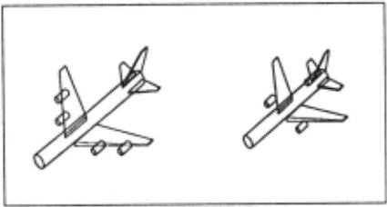
In the examples to be described here ACRONYM wu ginn a generic model or wide-bodied pauenger jet aircraft, along with elus specialisation· to L-10111 and Boeing-7471. The Boeing-747 clus had further subdue epecialisations to Boeing-7478 and Boeiog-747SP. The subeluees are do not completely partition their parent elu~e~. The clu1e1 are described by sets of constraints on some 30 quantillers. Figure 3.1 shows inetanees of the two major modeled clu~e~ ol jet aircraft. These diagrams were draw by AcRONYM from the models given it to carry out the image interpretations. The conetraiDta for the generic clue of wide bodied jets are giTen in fi&ure 3.2. Units are meten.
The camera wu modeled u being. between 1000 and 12000 meten abaft the ground. Thus there is little a priori knowledge ol the seale or the images. A specific focal ratio wu giYen: 20. (Similar interpretations have been carried out with a Tariable focal ratio, but then the final constraints on camera height and focal ratio are coupled, and not u clear for illustrative purposes - no accuracy is loet due to the ooo-lioearities that are introduced into the constraints, althouah both computation time and garbage collection time are inereaaed.)
The aircraft models, the camera model and the number or pixela in each dimenaioo of the image (512 X 512 in these examples) were the only pieces of world knowledge input to AcRONYM. It hu no special knowledge of aerial scenes: all ita rules are about geometry and algebraic manipulation. These were applied to the particular generic models it wu giTen, to make predictions and then to carry out inter· pretatiooe.
Figures 3.3 through 3.5 show three example· of interpretations carried out by A c RONYM. In each ease part a is a half-tone or the original grey level image. The b venion is the reault of applying the line finder of Nevatia and Babu J10J . That lioe finder wu designed to find linear features such u roado and rivers in aerial photoo. Close examination of reoulta on these images indicate many erron, and undue enlargement in width of narrow linear featureo. It also produeeo many noioe edgeo in in amooth brightneu gradient. (not viaible at the resolu· tion of the reproduction· or these figurea). These edge· are the loweet level input to A c RONYM.
An edge linker ]5) il directed by the predictions to look ror ribbon· and ellip1e1. lo thia ease there is Yery little a priori information about the scale of the images. The c Yerlionl or each figure show the ribbon· fitted to the lioked edges when it il searching for candidate matehea for the fuselage and wing· of aircraft. There ie nen further degredation of image information at this etage. Thia is the only data which the A CRONYM reuoning ayatem io given to interpret . Notice that in the figure 3.5 almoet all the ahapes correaponding to aircraft are loet. Quite a few aircraft in 3.4 are lost also. Besides losing many shapea, the combination or the edge Iinder and edge linker cooopire to give very inaccurate image meuurementa. We assume all image meaourementa have a ±30% error, except that for very omall meaaurements, we uoume that pixel noioe awampa even thooe error eatimateo. Then the error il estimated to be inversely proportional to the meuurement with a 2 pixel meaaurement admitting a 100% error . Thus the data which ACRONYM really geta to work with io conoiderably more fuuy than indicated by the the c eerie· or figures.
We intend to make use of new and better low Jeye) descriptive proeeslel being developped in our laboratory by other reaearehen u soon u they become robust enough for every day uoe (e.g. Baker Jl) whoae descriptions from stereo will also include aurface and depth information).
Despite this very noisy descriptive data A CRONYM makes good interpretation· of the images. The d eeriea of figures ahow ita inter· pretationa with the ribbona labeled by what part or the model they were matched to. (The numben which may be unreadable in 3.3d show the grouping· into individual aircraft .)
A CRONYM first uaes the moat general aet of eonatraints, those usoeiated with the generic class of wide- bodied jets, when carrying out intitial prediction and interpretation. Interpretation adda additional conotrainta for each hypothesised aircraft inotanee. For example in finding the correspondences in figure 3.4d constraint. were added which eventually constrained the IING_IIDTH (the width of the wings where they attach to fuselage) to lie in the range ]7, 10.5677531) compared to the modeled bounds of ]7, 12). The height of the camera, modeled to lie in the range ]1000, 12000) io constrained by the interpretation to the range [2199, 3322) .
Once a conaistent match or partial match to a geometric model baa been round in the context or some set or conatrainh (model elua), it eaey to check whether it might also be an instance or a eubelaaa. We need only add the extra constraint· associated with the eubelus and check for conoiateney with those already implied by the interpreta tion using the <:MS aa described in section 2.1. The aircraft located in 3.4d il conlistent with the constraint. for an L- 1011 , but not for a Boeing-7 47. Examination of the image· by the author had prnioualy indicated that the aircraft wu an L- 1011 . The additional symbolic conetrainta implied by accepting that the aircraft io in fact an L-1011 propagate through the entire constraint set. Although the conetraiota deeribing an L-1011 do not include conatrainta on camera hei&ht, the back eonotrainto deduced during interpretation relate quantifer1 repre senting eueh quantitieo u length of the wingo to the height (and focal ratio in the more general eaae ). Thua the height of the camera il fur· ther constrained in 3.4d to lie in the range ]2356, 2489). Recall that all image meaauremenh were subject to ±30% errors, and that thil eotimate baa taken all aueh errors into account.
Figure 3.3d indieatea matebea were found for three airplanes. Examination of the data in 3.3c indicatea that this ia the beet that could be expected. Note however that only partial matches were found in all three eaaeo. For such amall ribbon· errors were apparently larger than tbe generouo estimate used . The fuselage ribbon in the leftmost aircraft (number I) for instance faila to pau the coarae filtering otage. Deopite the partial match, this particular aircraft is found to be consistent with the constraints for an L- 1011, but not conaiatent with those of a Boeing- 747. Ag..in this i1 correct.
The other two aircraft identified are even more interesting. The author bad thought from cuual inspection of the grey leYel imace that they were inat&Dcea of Boeing- 747a. They both gave matcbn conaiatent with the clua of wide- bodied jeta. Aa expected neither wu conaiatent with the extra coatrainta of an L- I 0 I I. However, althoqb each individual parameter range from the interpretation conatraint Mtl wu conaiatent with the individual parameter value or range for the clua of Boeing-747a, neither aet of conatrainta wu conaiatent witb that aubclua (the conatrainta contain much finer information than juat the parameter rangea - in the aame inanner u in the example abafe where conatraintl on wing length propagate to constrain the camera height). On cloae examination of the grey-level image it wu determined that the aircraft were not in fact Boeing-747'·· The author uaed the fact that they were much omaller than the L-1011 to make that deduction, but ACRONYMmade the deduction at the local level before conaideriq compariaona between aircraft.
The aircraft (probably Boeing-707's) are in fact too omall to be wide- bodied jeta of any type. Since the ocale of the image ia unknown a priori this can not be deduced locally. However it is re8ected in the height eotimatea derived at the local level - 15400, 82261 interpreting the L- 1011 juat aa a generic wide-body, (15786, 6170] u an L-1011), and 19007, 11846] for the rightmoat, aircraft . Thus ACRONYM deducea that either the left aircraft ia a wide-body and the othera are not, or the right two are wide- bodiea and the left one is not (it ia too biJ).
Finally note that geometrically there were other candidate. for aircraft in the ribbons of figure 3.3c. For instance the wing of the aircraft juat to the right of thoae indentified and a ribbon found for ita passenger ramp could be the two wings of an aircaft with a fueelage missing between them. In fact these two ribbons were instantiat,ed u an aircaft on the basia of the coarse filtera on the nodes and area. HoweYer the aet of back conatrainta they generat,ed were mutually inconaiatent.
Thus we can see from the example· that even with very poor and noisy data the combined use of geometry and aymbolic algebraic conatraints can lead to accurate image interpretation·. The ayatem ahould be tested on more accurate low level data to fully evaluate the power of thia approach.
@inproceedings{ijcai1981p115,
  title     = {Model-Based Three Dimensional Interpretations of Two Dimensional Images},
  author    = {Brooks, Rodney A.},
  booktitle = {Proceedings of the Seventh International Joint Conference on
               Artificial Intelligence, {IJCAI-81}},
  publisher = {International Joint Conferences on Artificial Intelligence},
  editor    = {Patrick J. Hayes},
  pages     = {619--623},
  year      = {1981},
  month     = {8},
  note      = {Vision: 3-d},
  url       = {https://ijcai.org/proceedings/1981/115},
}
TY - CPAPER TI - Model-Based Three Dimensional Interpretations of Two Dimensional Images AU - Brooks, Rodney A. T2 - Proceedings of the Seventh International Joint Conference on Artificial Intelligence, IJCAI-81 PB - International Joint Conferences on Artificial Intelligence PY - 1981 SP - 619 EP - 623 UR - https://ijcai.org/proceedings/1981/115 ER -Copied
Machine-readable versions of this paper, for tools and AI agents:





