
Resolution Plans in Theorem Proving
Proceedings of the Sixth International Joint Conference on Artificial Intelligence. .
© 1979 International Joint Conferences on Artificial Intelligence
Abstract
Briefly, an example of a resolution plan can be described as follows: Let Ll v A and L2 v B be two clauses, where Ll and L2 are literals, and A and B are clauses. If Ll and L2 can be made complementary by some substitution, we shall call A v B (Ll,L2) a resolution plan. In general, a resolution plan is represented by C (Ll,Ml) ••. (Lr,Mr) , where Ll,Ml, ... ,Lr,Mr are literals, and Cis a clause. If Cis empty, (Ll,Ml) .•• (Lr,Mr) is called a total plan. The total plan corresponds to a proof if there is a unifier which simultaneously make (Li,Mi) complementary, i•l, ••. ,r. As shown elsewhere, the total plan approach can eliminate redundancies. In this paper, we shall show that all the strategies developed for resolution can be used to generate total plans.
- Chang, C.L., and Lee, R.C.T. (1973): Symbolic logic and mechanical theorem proving, Academic Press, New York.
- Chang, C.L., and Slagle, J.R. (1977): Usin~ rewriting rules for connection graphs to prove theorems, IBM Research Report RJ2117, San Jose, Ca. (To appear in Artificial Intelligence, 1979.)
- Kowalski, R., and Kuhner, D. (1971): Linear resolution with selection function, Artificial Intelligence 2, 227-260.
- Kowalski, R. (1975): A proof procedure using connection graphs, JACM 22, 4, 572-595.
- Robinson, J.A. (1965a): A machine-oriented logic based on the resolution principle, JACM 12, 1, 23-41.
- Robinson, J.A. (1965b): Automatic deduction with hyper-resolution, Internat. J. Comput. Math. 1, 227-234.
- Sickel, S. (1976): Clause interconnectivity graphs in theorem proving, IEEE Transactions on Computers, C-25, 823-834.
- Wos, L., Robinson, G.A., and Carson, D.F. (1965): Efficiency and completeness of the set of support strategy in theorem proving, JACM 12, 4, 536-541.
References were extracted automatically from the PDF and may contain errors.
Full text extracted automatically from the PDF; figures, tables and equations may differ. The PDF is the version of record.
1. INTRODUCTION
In [Chang and Slagle 1977], the concept of to ta l plans for proving theorems in first order logi c was proposed. A total plan is denoted by a sequence of pairs of literals, (Ll,Ml) ..· (Lr,Mr). If there is a suQstitution 8 that can make each of (Ll,Ml)8, .. . ,(Lr,Mr)8 a compl ementary pair of literals, the plan is said to be acceptable, and 8 is called a solution . In [Chang and Slagle 1977], a method based upon rewriting rules for generating total pl ans has been proposed. In this paper, we shall show that we can use resolution s trategies [Chang and Lee 1973, Kowalski and Kuhner 1971, Kowalski 1975, Robinson 1965a, 1965b, Wos et al. 1965] to generate total plans. This is done by generating resolution plans. Formal definitions of resolution plans will be given in the sequel. They are defined i n terms of notation of literals, instead of literals themselves. Because of this, un i f ication is not actually carried out during generations of resolution plans. This is in cons trast to resolution where unification has t o be performed. Therefore, it, is faster to generate resolution plans than resolvents.
In the following, we shall first give connection graphs, then we shall define various resolution plans such as binary resolution plans, hyper resolution plans, linear resolution plans, etc.
2. CONNECTION GRAPHS
The concept of a connection graph has been used in [Kowalski 1975, Sickel 1976]. Essentially, a connection graph is a data structure for a set of clauses indicating possible refutations. We shall now give a definition of a connection graph.
A pair of literals Ll and 12 are called potentially complementary if Ll and L2 can be made complementary by applying some substitution, after renaming variables so that
Ll and L2 share no variables.
A connection graph for a set S of clauses is
constructed as follows:
- Every clause in S appears in the graph exactly once;
(2) For every clause, Ll v ··. v Ln, inS, where Ll, ·.. ,Ln are literals, it is represented in the graph as

(3) For every pair of potentially complementary literals, draw an edge connecting the literals. (Note that edges between literals in the same clause are allowed.)
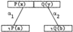
Example !· Fig. 2 is a connection graph for the set, {P(x) v Q(y), ,P(a), ,q(b)}.
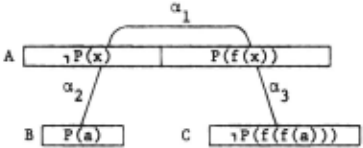
Example 1· Fig. 3 is a connection graph for the set, {,P(x) v P(f(x)), P(a), ,p(f(f(a)))}. Note that there is an edge connecting literals ,p(x) and P(f(x)) in the same clause.
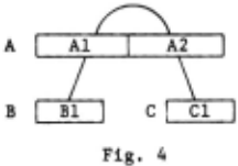
In the sequel, we shall label a clause by a distinct name and then refer to a literal in the clause by its position in the clause. That is, if C is a clause, then Cn is the n-th literal (counting from the left) of clause C, where n is an integer. By this convention, Fig. 3 will be represented by Fig. 4.
3. BINARY RESOLUTION PLANS
In terms of a connection graph for a set S of clauses, we now give the following definitions.
A clause plan is represented by a clause followed by a sequence of pairs of literals. A clause plan can be represented as
where Li, Mj and Nj, i·l, .·· ,p, j·l, ··· ,q, are literals. We call Ll v ·.. v Lp a clause segment, and (Ml,Nl) ··· (Mq,Nq) a plan segment of the clause plan. A clause plan is called a total plan if and only if its clause segment is empty.
Definition. Let two clause plans A and B respectively be denoted by
A·C P
B·D Q,
where C and D are the respective clause segments of A and B, and P and Q are the respective plan segments of A and B. If there are literals Ll, ··· ,Lm inC, and Ml, ··. ,Mn in D such that there are edges in a connection graph connecting every literal of Ll, ... ,Lm to every literal of ~l, ·.· ,Mn, then the clause plan
where C'·{Ll, ··. ,Lm} and D'·{Ml, ··· ,Mn}, is called a binary resolution plan of A and B. Note that (Ll,Ml)(Ll,~2) ..· (Lm,Mn) is a cartesian product of C' and D', and may be represented by (C' ,D').
Example l· Let A·P(x) V Q(x) and B·,P(a) v R(x). Using the positions of literals in the clause to name the literals, A and B are represented as
where Al, A2, Bland B2 are P(x), Q(x), 1P(a) and R(x), respectively. Note that using the notation in the above definition, C·{Al,A2} and D·{Bl,B2}, and both P and Q are emptv. Since Al and Bl are complementarilv unifiable, we choose C'K{Al} and D'·{Bl}. -Therefore, a resolution plan is obtained as follows:
(C-C')U(D-D')(C',D')P Q
- ({Al,A2}-{Al})U({Bl,B2}-{Bl})({Al},{Bl})
- {A2}U{B2}(Al,Bl)
- {A2,B2}(Al,Bl)
- A2 v B2(Al,Bl).
We can use resolution strategies to generate total plans for refutations. That is, ~iven a set S of clauses, we first build a connection graph for s. Then, to check whether or not a pair of literals are potentially complementary, we need only to look at the connection graph to see if there is an edge connecting the literals. Once we have a connection graph, resolution plans can be generated faster than resolution because unification does not have to be performed. A total plan is a clause plan whose clause segment is empty. We can use resolution strategies to generate total plans. Once a total plan is generated, we then perform unif i cation at the last step to check whether or not the plan is acceptable.
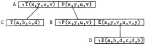
Example i· Consider the set S of the following clauses,
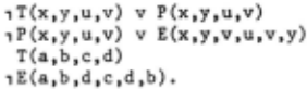
The connection graph for S is shown in Fig. 5.
Using literal names, Fig. 5 can be represented by Fig. 6.
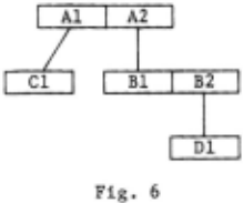
Now , using Fig. 6, we can generate the fol lowing resolution plans:
| (1 ) Al v A2 (2) Bl v B2 (3) Cl (4) Dl (5) Bl (B2,Dl) (6) Al (Bl,A2) | a clause in s a clause in s a clause in s a clause in s a resolution plan of (2) and (4) a resolution plan of (1) and (5) |
(7) (Al,Cl) (Bl,A2) (B2,Dl) a resolution plan of (3) and (6).
Now, since we want to perform unification, we first need to rename variables. As discussed in [Chang and Slagle 1977], for the total plan (Al,Cl)(Bl,A2)(B2,Dl), all literals belong to a clause are linked to a common dot. Therefore, we obtain the following linked plan,
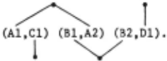
The above linked plan can also be represented as
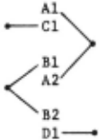
Substituting the real literals for Al, A2, Bl, B2, Cl and Dl in the linked plan, we obtain
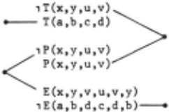
Renaming the variables so that no clauses share variables in common, we obtain
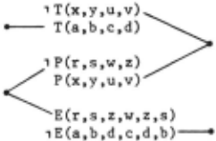
Unifying the two expressions,
we obtain a substitution
e = {a/x, b/y , c/u, d/v, a/r, b/s, c /w, d/z } .
This substitution is a solution of the set M of the following clauses,
because M6 is
and is truth-functionally unsatisfiable.
4. LINEAR AND SET-OF-SUPPORT RESOLUTION PLANS
Definition. Given a connection graph for a set S of clauses, Cn is called a linear resolution plan if and only if it is obtained as shown in Fig. 7, where c 0 is a clause inS, and for i·O,l, .·· ,n-1, (a) Ci+l is a resolution plan of Ci and Bi, and (b) each Bi is either in S, or is a cj for some j, j<i.
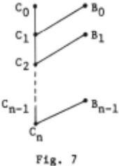
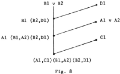
Example 1· The deduction obtained in Example 4 is a linear deduction as shown in Fig. 8. That is, the total plan, (Al,Cl)(Bl,A2)(B2,Dl), is a linear resolution plan.
Definition. A subset T of a set S of clauses is called a set of support of S if (S-T) is satisfiable. A set-of-support resolution plan is a binary resolution plan of two clauses that are not both from (S-T).
Example ~· Consider the set S of clauses given in Example 4. Now, if we let T be the set {,E(a,b,d,c,d,b)}, then the deduction iiven in Fig. 8 is also a set-of-support deduction. (Note that in general, a set-of-support deduction needs not be a linear deduction.)
5. HYPER RESOLUTION PLANS
In order to define a hyper resolution plan, we shall name atomic formulas in every literal of a clause, instead of naming the literal itsel f as given in the previous sections. That is, if Cis a clause, then the ·n-th literal of clause C is named as Cn if the literal is positive, and named as 1Cn if it is negative. For example, if
then A and B can be respectively represented as
We say that a clause plan is positive if its clause segment is positive. Otherwise, it is negative.
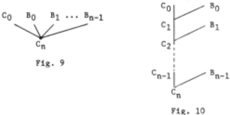
Definition. Let C be a negative clause plan, and let Bo,Bl·····Bn-1 be positive clause plans. Then, Cn is a~ resolution plan, as shown in Fig. 9, if Cn is a positive clause plan obtained by a deduction shown in Fig . 10 , where Ci is a binary resolution plan of Ci- 1 and Bi-1· i·l, ·.· ,n.
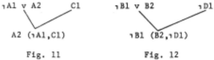
Example l· Consider the set S of clauses given in Example 4. Using the clause names in Fig. 5, we can represent the clauses in S as fol lows:
- ,Al v A2
- ( 2) 1 Bl v B2
- Cl
- 1 Dl.
Then, the deduction shown in Fig. 11 is a hyper deduction, while the one shown in Fig. 12 is no t .
6. RENAMING VARIABLES AND HANDLING DUPLICATE CLAUSE PLANS
One of the important steps in theorem proving i s renaming variables. In ordinary resolution, before a resolution is performed, variables in clauses need to be renamed so that the clauses share no variables in common. Herbrand's Theorem says that a set S of clauses is unsatisfiable if and only if there is a finite unsatisfiable set S' of ground instances of clauses of S. Renaming variables is closely re la ted t o Herbrand's Theorem because more than one ground instances in S' may come from the same c lause C in S, and the ground instances are essentially obtained by first renaming variables in copies of C.
Given a set S of clauses, we first generate a deduction of a total plan from S, and then check if the total plan is acceptable by r enaming variables and by performing unif i cation . In the deduction of the total plan , the same clause plan may appear more than once. In this case, we shall use primes to distinguish the different copies of the clause plan. This i s illustrated by the following example .
Exampl e ~· Cons ider the set S of clauses given in Exampl e 2. That is, S consists of the f ollowing c lauses
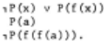
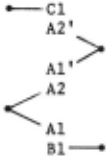
The connec tion graph of S is shown in Fig . 3. Using li t eral names , Fig. 3 can be represented by Fig. 13.
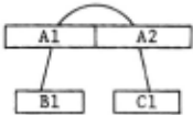
Using Fig. 13, we can generate a deduction of a total plan shown in Fig. 14.
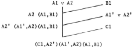
Note that two copies of (Al v A2) are used in the deduction, and we use (Al' v A2') to represent the second copy. By linking literals belonging to the same copy of a clause, we obtain
Substituting the real literals for Al, A2, Al', A2', Bl and Cl, we obtain
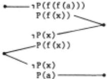
Renaming the variables so that no clauses share variables in common, we obtain
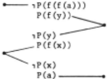
P(a)---...
Unifying the two expression,
we obtain a substitution
This substitution is a solution of the set M of the following clauses,
l 1 P(x) vP(f(x)) ,P(y) v P(f(y)) P(a) ,p(f(f(a))),because Me is
l ,P(a) v P(f(a)) ,p(f(a)) v P(f(f(a))) P(a) ,p(f(f(a))),and M6 is truth-functionally unsatisfiable.
7. CONCLUSIONS
We have defined various resolution plans. These plans are obtained from the connection graph of a set S of clauses. To generate resolution plans, no unification needs to be performed. Therefore, it is faster to generate a resolution plan than to generate a resolvent. Unification is performed only at the end of a proof. One of the advantages of using the resolution plan method is that all the strategies proposed for resolution can be directly applied to generate resolution plans.
ACKNOWLEDGMENTS
The author would like to thank Dr. J. R. Slagle of Naval Research Laboratory, Washington, D.C. for his conversations.
@inproceedings{ijcai1979p36,
  title     = {Resolution Plans in Theorem Proving},
  author    = {Chang, C. L.},
  booktitle = {Proceedings of the Sixth International Joint Conference on
               Artificial Intelligence, {IJCAI-79}},
  publisher = {International Joint Conferences on Artificial Intelligence},
  editor    = {Bruce G. Buchanan},
  year      = {1979},
  month     = {8},
  url       = {https://ijcai.org/proceedings/1979/36},
}
TY - CPAPER TI - Resolution Plans in Theorem Proving AU - Chang, C. L. T2 - Proceedings of the Sixth International Joint Conference on Artificial Intelligence, IJCAI-79 PB - International Joint Conferences on Artificial Intelligence PY - 1979 UR - https://ijcai.org/proceedings/1979/36 ER -Copied
Machine-readable versions of this paper, for tools and AI agents:





