
An Automobile with Artificial Intelligence
Proceedings of the Sixth International Joint Conference on Artificial Intelligence. .
© 1979 International Joint Conferences on Artificial Intelligence
Abstract
This paper describes an automobile with artificial intelligence, which consists of a road pattern recognition unit and a problem solving unit. The vehicle is completely autonomous and can be driven without a human driver. The road pattern recognition unit involving a pair of TV cameras and a processing unit identifies obstacles in front of the vehicle and outputs data regarding to the locations of the obstacles. The problem solving unit is a microcomputer system and determines control optimal to the environment around the vehicle based on the data. The algorithm employed in it is a table-look-up method, in which the location of the optimal control is addressed in the table by key words generated from the data. The table was heuristically made by means of digital simulation. The vehicle was successfully driven under various road environments at the speed within 30 Km/h.
Full text extracted automatically from the PDF; figures, tables and equations may differ. The PDF is the version of record.
1. INTRODUCTION
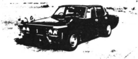
The origins of an automobile with artificial intelligence, called an intelligent car, can be found in both the automatically driven vehicle [1] and the intelligent robot [2]. Due to the guidance system for the automatically driven vehicle, it had one serious defect that it could neither detect nor avoid obstacles on its path. Based on the performance of artificial intelli gence the automatically driven vehicle was im proved to the intelligent car shown in Fig. 1. It consists of a road pattern recognition unit and a problem solving unit. Then, it involves all the facilities to perform locomotion as an automobile and can move autonomously.
2. ROAD PATTERN RECOGNITION
The road pattern recognition unit functions to clarify presence of obstacles in the view field in front of the vehicle. The unit consists of a pair of TV cameras and a processing unit for video signals from them. The cameras are mounted in the front part of the vehicle with a fixed interval (50 em) along a vertical line as shown in Fig. 1.
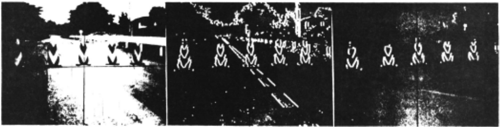
The principle of operation of the unit is shown in Fig. 2, and processing in it is shown in Fig. 3 (a)-( c) which correspond to (a)-(c) in Fig. 2. The two images on the TV cameras, one of which is shown in Fig. 3(a), shift vertically from each other due to the camera positions, and scanning them synchronously and vertically gen erates two video signals. By processing the signals two pulse trains indicating brightness/ darkness changing points (BDCP), one of which is shown in Fig. 3(b), are obtained. One train is delayed for a fixed time corresponding to a distance of a range where an obstacle is to be searched. The delay compensates the shift be tween the images. Then, the trains are checked if any part of them has same pulse sequences each other, and this results in detection of obstacles as shown in Fig. 3(c), where just real obstacles including some illusion are shown. In Fig. 3(c) the center line is rejected as it does not have any height, and the guard rail is also rejected as it is out of the pres ent range. To cancel the illusion, height and width of obstacles are checked furthermore.

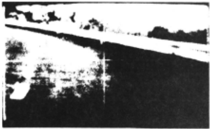
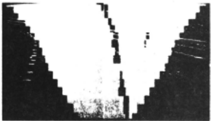
By employing different delays of more than one and the following circuits, the processing of the pulse trains is performed in parallel to identify obstacles in the wh~le view field. Processing the images shown in Fig. 4(a) as de scribed above results in identification of ob stacles in the view field shown in Fig. 4(b). The view field is quantized according to the ranges, in each of which obstacles are identi fied, and then the perspective form is converted to a plane figure form. The ·trapezoid in Fig.4 (b) is the view field in the plane figure and black parts in the center of it are the guard rail, i.e. obstacles.
The area of the view field is between 5 m and 20 m from the vehicle with viewing angle of 40 degree. The time required to identify obstacles is 33.3 msec for scanning one frame and 2.3 msec for processing after scanning.
3. ALGORITHM FOR DETERMINATION OF CONTROL
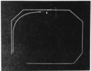
The problem solving unit determines control by using the data from the road pattern recognition unit. The purpose of the intelligent car is proper locomotion in road environments with safety, quickness and "keep left". Therefore the time required to determine control must be within 100 msec at most, because the vehicle running at 36 Km/h runs 1 m in 100 msec. To sat isfy this requirement, a table-look-up method is employed. In the method, control is retrieved by key words from a table. The key words are gen erated by logical operation upon the data from the pattern recognition unit and have relations to the location where the control is stored. The table was made heuristically by computer simulation. Fig. 5 shows the simulation. On the display the vehicle, its view field, its traj ecto ry and the left guard rail are drawn.
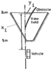
Af ter the simulation, the following algorithm was employed in the intelligent car. By defin ing xi(i=l to 16, xi=5 to 20) and yi(y .=-32 to 96) as shown in Fig. 6, the road is clkssified into five categories: 1) course following, 2) obstacles on the road, 3) left turning, 4) righ t turning and 5) dead end. In the cases of 1) or 2) a set of (xi,yi) maximizing y 1 /xi is the key words. In the cases of 3) or 4) a set of (xi,yi) indicating the corner of the turning is a lso Ehe key words. To make the size of the table small, 16 kinds of xi are decreased to 8, and 128 kinds of yi to 32. Therefore the table has 8 x 32 elements.
The problem solving unit consists of a micro computer system including a micro CPU, RAMs (8 KB), ROMs (3 KB), I/O interfacing LSis, and A/D and IJ /A converters. The time required to get control is very short and within 33.3 msec in most cases and 100 msec at most, which inc lude just processing in the microcomputer. A human driver usually requires more than 0.4 sec.
4. EXPERIMENTS
4 . 1 The Intelligent Car
The automobile is a compact car with a torque converter, some sensors and actuators. The sensors include a speed s ensor for the vehi c le and a angle sensor for the steering wheel. The actuators include a hydraulic actuator for the steering wheel, an electric motor for throttle valves and vacuum servo brakes.
4. 2 Experimental Results
The experiments were conducted in the test truck of our laboratory. Some results are shown in Figs. 7 and 8.
5. CONCLUSION
Artificial intelligence including both pattern recognition and problem solving for locomotion has been implemented in both software and hard ware to the intelligent car. The vehicle was successfully driven under various road environ ments at the speed within 30 Km/h.
@inproceedings{ijcai1979p197,
  title     = {An Automobile with Artificial Intelligence},
  author    = {Tsugawa, Sadayuki and Yatabe, Teruo and Hirose, Takeshi and Matsumoto, Shuntetsu},
  booktitle = {Proceedings of the Sixth International Joint Conference on
               Artificial Intelligence, {IJCAI-79}},
  publisher = {International Joint Conferences on Artificial Intelligence},
  editor    = {Bruce G. Buchanan},
  year      = {1979},
  month     = {8},
  url       = {https://ijcai.org/proceedings/1979/197},
}
TY - CPAPER TI - An Automobile with Artificial Intelligence AU - Tsugawa, Sadayuki AU - Yatabe, Teruo AU - Hirose, Takeshi AU - Matsumoto, Shuntetsu T2 - Proceedings of the Sixth International Joint Conference on Artificial Intelligence, IJCAI-79 PB - International Joint Conferences on Artificial Intelligence PY - 1979 UR - https://ijcai.org/proceedings/1979/197 ER -Copied
Machine-readable versions of this paper, for tools and AI agents:





