
Three-Dimensional Modeling
Proceedings of the Fifth International Joint Conference on Artificial Intelligence. Vision. Pages 649-654.
© 1977 International Joint Conferences on Artificial Intelligence
Abstract
A scheme used in building models of threedimensional objects through binocular and motion parallax analyses is presented. Some preliminary results in using the models for recognition are described, and a discussion of the major objectives summarizes the rationale of the work. The principal emphasis throughout the paper will be that effective vision requires flexible, domain-free, three-dimensional modelling.
Full text extracted automatically from the PDF; figures, tables and equations may differ. The PDF is the version of record.
Abstract
A scheme used in building models of three - dimensional objects through binocular and motion parallax analyses is presented. Some preliminary results in using the models for recognition are described, and a discussion of the major objectives summarizes the rationale of the work. The principal emphasis throughout the paper will be that effective vision requires flexible, domain-free, three-dimensional modelling.
.InkQduction
Object recognition and scene analysis research systems may be categorized by the use they make of models. The 'hard-wired' approach so common in areas such as chromosome classification, and typical 'blocks world' analysis places them in the loHer rank of modelling varieties. The descriptive primitives and their inter relationships which determine classifications are embedded implicitly in the operation of these schemes, and accommodation to other domains is out of the question. Increased flexibility can be attained through the more modular approach of supplying the system . with certain pre-defined feature primitives from which it can compose appropriate object descriptions. This technique can be seen in the two-dimensional vision works of Roberts, Barrow, Widrow, and Turner, and has a very significant presence in many Computer Aided-Design schemes ([Braid], [Voelcker]) and the three-dimensional work of Popplestone et al. However, even in the vision work here the dependence on a particular domain is very heavy. No general shape descriptive mechanism is available, and each form to be recognized must be anticipated and encoded (or programmed) beforehand. With the static nature of their feature sets and their limited descriptive range, these systems have only cosmetic advantage over
the 'hard-wired' approach.
It is common practice in well defined, task-oriented problems to introduce such domain-specific, insight-driven program tailoring whenever it will lead to more direct and efficient solutions. . In these cases, purist attitudes, arguing for generality and flexibility, should rightly be abandoned. The long term prospects of
·where the author is currently in a PhD program
THREE-DIMENSIONAL MODELLING
Harlyn Baker Machine Intelligence Research Unit Edinburgh University and
The Coordinated Science Laboratory* University of Illinois at Urbana-Champaign Urbana, Illinois 61801
machine v~s~on, however, cannot be met by extension of programs dedicated and optimized in their performance to specific domains. In this, generality and flexibility will be essential
ingredients.
A system, to show competence in visual processing, must, among other things,· be able to both use and construct fully descriptive (and this means three - dimensional) models of the objects in its environment. It must be able to look out on a scene and build models of whatever is there (hands, peoole, cars, etc.), and then be able to manipulate these models, comparing them with other descriptions it may build in analyzing some later viewed scene. Regarded in this way, the pro~ram's role will be seen to be quite passive it will not be acting~ the models, but as an intelligent interface between those in its memory and the presented visual data. Only in this way, with specific domain dependent knowledge removed from the processing can the wanted extensibility be sought.
Note that the model building required of such a system is, in a way, complementary to recognition. While recognition is a process of taking descriptions from memory and using them in the analysis of presented visual images, modelling is the process of analyzing such visual images to build descriptions of the objects from the present environment. Since recognizing is associating the experiences of the present with those of the past, it is only appropriate that a recognition scheme also be a modelling scheme .. it needs to keep a
record of its past experience.
A large part of the reason for the proliferation of domain-specific vision research may lie in the myopia inherent in the way sensors have been used. Typically, an entire analysis is based upon a single television image. This may seem to be a reasonable compromise, as it does appear to allow the feeling and flavour of vision without the complications of three - dimensional or time analysis. Unfortunately such a process has a striking resemblance to a stationary, one-eyed fly's single-shot vision, and provides too weak a paradigm when the ever-present comparison is with that of our own human sight. A machine v~s~on system, as the human system it tries to simulate, must be able to increase and refine the understanding it has of its environment working in a domain of three-dimensional objects, its representation must encompass that three - dimensionality, yet a single (note ~) projected image of some unknown object can reveal very little of its 3-D nature. Consider the task of trying to extract sufficient information from a television image not just to recognize some object, but to create a description that will enable that object to be recognized whenever it is seen again, in any orientation, and under any viewing conditions. This weakness of the single - view approach has been a re-enforcement for pre-analyzing two- dimensional projections, and thus imposing on the processing a domain of expectation. An escape from this domain dependence trap calls for a different, considerably stronger paradigm.
It was my intention in this work to explore the possibilities of machine vision in an unrestricted domain of objects, with viewing conditions as near those in which the human system operates as practicable (this excluded lasers, and other such direct ranging devices). The necessity of having a three-dimensional representation led me to consider ways of representing surface shape, and, in turn, three-dimensional object structure, and the need to obtain this structure through a television camera led me to the problem of determining means of making such three dimensional measures.
Humans use binocular and motion parallax (as well as other innate and learned techniques) in distinguishing depths, and I determined to concentrate on seeing how an analysis of this binocular and motion parallax, as obtained through a mobile television camera, could reveal three - dimensional shape and relationships. (Similar approaches can be seen in the work of [Baumgart], which started earlier and ran concurrently with this work, and the later work of [Burr].)
It is important not to build into a vision system any specific knowledge of shapes. This means we must exclude from consideration any process that takes regions from an image, infers their orientation from an analysis of shape (i.e., a circle may appear as an ellipse), and uses these inferred shapes as primitives in its model description. It is only after we determine a context, based on experience, that we can do this in our vision, and a virgin modelling system, having no experience, and knowing nothing of the context that experience teaches, should similarly have no preconceptions of shape or shape implications.
~~~ Irregularities ~ Building ~
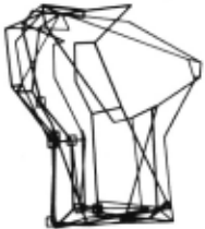
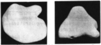
What I have done in this work in an attempt to keep shape preconceptions out of the processing is to chose a very low-level descriptive primitive, hopefully without a domain bias, and use this in specifying shape. The description is formed by locating particular second order irregularities in projected images, tracking them over a series of views, and building up a meshed network whose nodes are these irregularities (in 3 space), and whose arcs are the surface curvatures joining them. The model of a surface's shape, then, is this meshing of vectors and curvature descriptors to be visualized perhaps as a wire-meshed exoskeleton. An object whole, which may consist of many surfaces, is defined in a similar manner, with vectors locating and orienting its constituent surfaces. Figure 1 shows a single-surfaced object defined in this way.
The primitives of these shape descriptions are points of curvature irregularity those positions in the image where constant curvature arcs, fit ted to the contours (or ed~?;es) , terminate. These occur most prevalently where shape irregularity is densest, and, being local measures, allow the analysis to be much less susceptible to projective anomolies and occlusions (the total surface shape, being a complex of local shape, only loses definition at the occlusion). They are psychologically interesting, being measures of the most discriminative aspect of shape, its smoothness and irregularity (remember Attneave's cat), and their use as a metric puts no constraints on the type of shapes to be dealt with (any projected shape can be·closely approximated with circular arcs, even polyhedral edges).
The implementation forced several compromises in the professed intentions. Clearly, cluttered scenes were not allowed in the modelling phase. Objects studied were rigid, single-coloured, opaque solids (although earlier work was done with a multi-coloured object). A fixed camera frame made it necessary to rotate the objects, rather than the camera (for most purposes, these are equivalent).
The task of obtaining object descriptions of this form is implemented through two processes (programmed in Macro on a PDP-10). The first analyzes individual images of a scene, extracting contour descriptions based upon the irregularity measure. The second takes sequential pairs of such descriptions, correlates them (that is, correlates their irregularities), and constructs the meshed networks representing their shapes.
The protocol for the low level analysis is the following. An object, mounted on a spit, is photographed, the image analyzed, and the results of the analysis are passed to the correlation process. The object is then rotated on the spit (through a known angle) to a new orientation, where it is photographed, and the analysis repeated . Further rotations are made, each being followed by the image acquisition, analysis, and transmission to the correlator .
Each analysis first involves scanning the intensity array to find picture points that (probably) lie on region boundaries, a process which requires two passes over the array with a 2 by 1 pixel operator. The first pass locates the horizontal edges, the second the vertical (figure 2a). There is little of special significance in this aspect of the processing .. the edge points, or intensity discontinuities, are positioned where the intensity gradient is greatest in an area bounded by either near-homogeneous areas (typi~ally the middle of image regions), or intensity gradient inflections. Circular arcs are then fitted through these points. The endpoints, or junctions of these arcs are the curvature irregularities used in the correlation (figure 2b).
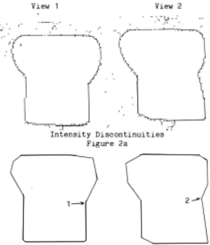
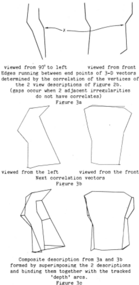
The correlation process operates on the output of two sequential low level analyses. It begins by finding corresponding regions in t he two views (using as measures distance apart, size, and average intensity). Once these are established, it selects corresponding curvature irregularities and, correlating them, determines the three dimensional vector they imply (figure 3a). The measures used in selecting corresponding curvature irregularities include the concavity or convexity, both at the junctions and in the arcs on either side (these are topological tests), and the magnitude of their separation and the direction of their vertex bisectors (positional tests). To determine the vector, the correlation process must know the equation of the rotational axis (the spit) lying in the plane of projection, its distance from the camera, and the rotational angle change, as well as the two - dimensional coordinates of the irregularities in the two views (the vector at point X in figure 3a was derived from the correlation of vertices 1 and 2 in figure 2b). Figure 3b shows the positions of vectors from the next correlation, and figure 3c shows the composite description after these 2 correlations.
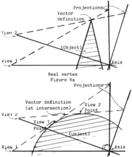
It isn't obvious, but this correlation works equally well for 'real' edge irregularities, such as the vertices of a cube, as it does for those on 'pseudo' edges, three-dimensional contours. With the former (figure 4a), the vector will actually locate the vertex (within the digitization error), while in the latter case, the vector will indicate a point near the surface lying between the irregularities seen in the two projected views (figure 4b). This may seem to be a flaw in the modelling, but is actually quite the opposite the distance above the surface is proportional to the angle of rotation and the convexity of the surface, and is not large - the arcs connecting these vectors (termed 'depth' arcs) literally hold the model together .
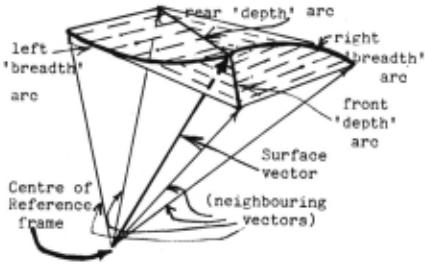
Each such vector may have up to four surface descriptor arcs leaving it (figure 5). Two of these may be to the left and right ('breadth' arcs), and run to vectors adjacent, and derived from the same two individual views. The other two may extend to the front and rear (these are 'depth' arcs .. notice those arcs in figure 3c which were not present in either figure 3a or 3b). The left/right arcs carry curvature information, as their shapes were seen in the two views correlated, but the depth arcs have no indication of curvature.. their shapes were not seen. In fact depth arcs are just inferred from the tracking of vectors as the object rotates (this is the motion component of the analysis). An ongoing clustering process collapses these 'depth' arcs when the irregularities they separate are within the digitization error of each other, and creates others when new irregularities approach earlier ones (the description is wrapping back around on itself).
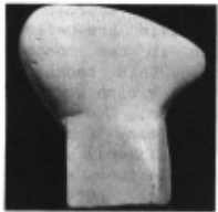
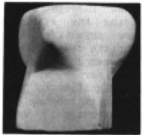
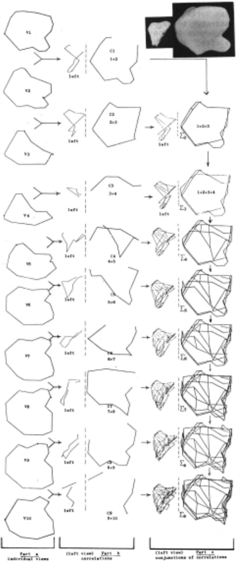
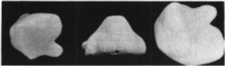
These vectors and arcs, then, are the basis for surface shape description. Since an object may consist of many surfaces, each is specified as a composite of its surface vectoral descriptions. (As mentioned earlier, the objects modelled were almost exclusively single-surfaced . ) Figure 7 shows the progression of the modelling through a sequence of ten views (in 20 degree increments) with the object of figure 6. Part 'a' is the individual regions as found in the intensity arrays, part 'b' shows the 'breadth' arcs formed from the correlations (viewed from 90°to the left, and from the front), while part 'c' indicates the composite descriptions as they are formed (successive 'breadth' arcs joined with their tracked 'depth' arcs), again viewed from 90° to the left, and from the front.
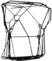
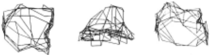
Figure 9 shows the completed model viewed roughly in the orientations depicted in figure 8. There are a few aberrant points on this model, notably in the left figure at the extreme bottom right and the top left. These arise from the correlation of irregularities whose local surface is nearly orthogonal to the rotational axis .. this error is difficult to avoid when only one axis is used. Two perpendicular axes can be handled in this modelling scheme, but tests were only carried out for the case of one axis. Details of the modelling, just mentioned here, are available in [Baker].
~~ Comparisons
As expressive as these descriptions may seem, they are surely too verbose to be used alone for object recognition, and it is at this point that our interest may turn to the use of shape primitives. However, for freedom from domain dependence, it is essential that any such primitives be abstracted only from the shape models in the modelling scheme's memory. That is, if it is to use shape feature primitives, they must be ones which it derives itself over a period of preliminary operation . ~!though essential, this is of course a gargantuan task. ~ subproblem here as well is that of being able to compare parts of such models so that common descriptions may be abstracted as shape primitives, to be then applied to the analysis of subsequently presented objects. An efficient recognition scheme will work with these abstracted primitives to partition models into more symbolic form, but of course this too requires vectoral comparisons. The comparison process is thus basic to both recognition and generalization, and the appropriateness of the representation will depend upon its ability to be used in such a model matching scheme.
Figure 10a ~epeats the model constructed for the object of figure 1. Figure 10b shows another model of the same object, but constructed from a different initial orientation (making it very unlikely that many, if any, of their corresponding vectors will be coincident) . The two models have between 80 and 100 vertex points (three dimensional vectors) each, which suggests that the straightforward approach of comparing all points in pairs would be impractical. It is also obvious that there needn't even be a 1 to 1 correspondence between the points on the two models. Although the vectors are derived by analyzing shape irregularities, these are projective measures, and with two arbitrary initial positionings, nothing can be assumed about their relative orientations or the relative locations of their surface vectors . If shape comparison is to proceed, something must be found that will allow these relations to be discovered.
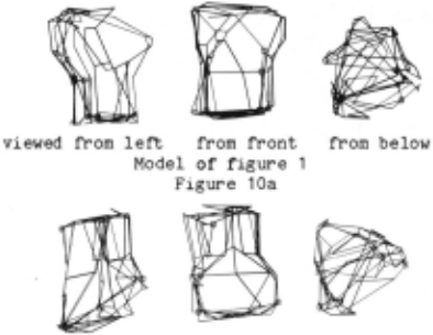
As each model is constructed, it is put in a pseudo-canonic form ('pseudo' because it cannot be guaranteed to be unique) . . it is reoriented about a coordinate frame defined by its greatest breadth, and two other axes calculated normal to this. Yet even this does not ensure a unique orientation, as the views used for the correlation are discrete projective slices, and an object having many similar large diameters could (depending upon the particular views seen) have any of them chosen as its maximal. To force a bit more order into the process, I assume that if two shapes are to be considered similar, then at least a certain number of their topologically significant features should correspond (note that the assumption could run into trouble where there is severe occlusion or where an object has a highly symmetric nature). This is implemented by keeping with each model a list of its 6 most concave or convex vertices (these characterize the local surface shape about a vector, and are indicated in figures lOa and lOb byD). The figure 6 is arbitrary, but must be at least 3 to enable the transformation equations to be determined (the more there are, the better the chance of finding a match, but equally the longer it may take to discover it). The problem of finding the possible relationship between the two shapes is now reduced to finding similar triangles in these 2 sets of 6 points (with the additional requirement that corresponding vertices be of the same type - either concave or convex) (figure 11). The similarity, rather than congruence, allows objects of different scale to be compared.
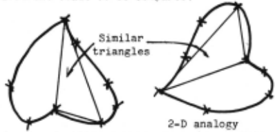
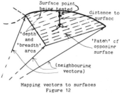
If no such pair of si~ilar triangles can be formed among these points, then the surfaces may be considered to be different ( ~ori th the above noted exceptions to the assumption). If there is such a pair, then the transformation that maps one set onto the other should equally map all points in that model onto the other model (however not necessarily in a point to point way). Comparing the shapes is then a matter of reorienting and translating successive vectors of the one model, and determining how close each lies to the surface of the other model. This is done by finding which 'patch' of the other surface each point projects onto and determining its distance from · that surface (figure 12). A recursive process crawls about on the two meshings, branching along each arc, and backing up when a node vector lies too far from its opposing surface.
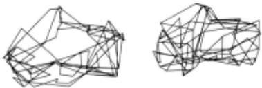
The theoretical error limit of the correlation process was about one fifth of an inch for the 90 by 90 images used (with a 9 inch field of view at about 5 feet), and the vector to surface distance allowed in the matching was twice this value. It would be possible (although it was not implemented) to look at the cumulative errors in point to surface mappings, and use these to adjust the initially inferred transformation equations. This would be of major advantage whenever the similar triangle vertices are located to one side of the surface, where the digitization and correlation inaccuracies could lead to minimal error in the transformation for points near the vertices but significant errors as the distance from them increases. Figure 13 shows both objects in the orientation in which they were successfully matched (80% of the points corresponded, while only 23% in the left model were successfully mapped onto the surface of the model in figure 9) .
It is not my intention to suggest from this preliminary matching success that the memory of models be used in this way, as the extraction and use of commonly occurring shapes is critical for a recognition scheme that hopes to work in anything resembling real time. But, as stated, this comparison procedure is an i~portant part of the generalizing, and it was necessary to show that the models could be manipulated and compared in this way.
Project;i..QM
My objective with this work now is to go back through much of it and bring it up working with larger (250 square) images of multi-coloured objects, then when satisfied with its performance at this level, to study the shape generalization problem. A few further, more futuristic, goals - model modification to contain 'dynamic' structure ~nformation (making 'working' models of non-rigid objects), and self-organization of model memory, to provide efficient, perhaps context-sensitive, retrieval - indicate the potential for further development within this modelling framework.
Imoortant l:Q.in.t§.
This approach, stepping into multiple - view analysis, marks a significant change from previous work in machine vision.
~ ~t§. ~ .valuable reconsideration Q[ programming m .QaQh... Established vision methods, where all information available to the analysis is presented in one single view, force the analysis to be temporally local with their over-riding demand for an interpretation, and make the system particularly sensitive to the destructive influence of view-point anomolies and image noise. The analysis of parallax, with its correlating of many sequential images, allows one to loosen this dependence on 'clean' pictures, and leave the generalizing over errors or ambiguities of analysis to the more capable higher level process that works in time. ('Dirty', or structurally discontinuous sequences of pictures don't exactly help, but neither are they catastrophic.)
Different ~till ~ ~ approach 1& ~ ~ Qf objects .an..Q. ~ fQr. concise ~ detailed descriptive models. As much as its uniqueness was underplayed in the discussion of shape matching, there is truly something canonic, and even psychologically significant, in the use of this irregularity-based representation.
.B.l.l.t. .!!lMt. significant ll ~ ~ 1hi.§. ~ towards establishing a ~ reasonable kinQ Qf initial ~ knowledge in~ system. Previous efforts in computer vision have involved embedding a great deal of domain-specific knowledge (eg. the domain of tri-hedral convex polyhedra) into the workings of the process. In these systems the initial state knowledge has served to define and constrain the environment. Instead, this system is given, through an understanding of parallax, working knowledge of the behavior of physical objects in three space. Having ways of manipulating the environment, it is able to exploit this behavioral knowledge in analyzing the scene. .1M. contrast, then., l..i.e..:!. ..in. .s..;i.ting_ 1he_ ~ .D.Q..t specific knowledge Qf ~ fiu::w.s. in. it..s_ world, hut knowledge specific tQ ~ determining those forms.
.A.Q.kn.QH.kdg em en t
Part of this work was supported by two research contracts from the National Laboratory to Professor Donald Michie, Intelligence Research Unit, Edinburgh Edinburgh, Scotland. successive Engineering The Machine University,
@inproceedings{ijcai1977p154,
  title     = {Three-Dimensional Modeling},
  author    = {Baker, H.},
  booktitle = {Proceedings of the Fifth International Joint Conference on
               Artificial Intelligence, {IJCAI-77}},
  publisher = {International Joint Conferences on Artificial Intelligence},
  editor    = {Raj Reddy},
  pages     = {649--654},
  year      = {1977},
  note      = {Vision},
  url       = {https://ijcai.org/proceedings/1977/154},
}
TY - CPAPER TI - Three-Dimensional Modeling AU - Baker, H. T2 - Proceedings of the Fifth International Joint Conference on Artificial Intelligence, IJCAI-77 PB - International Joint Conferences on Artificial Intelligence PY - 1977 SP - 649 EP - 654 UR - https://ijcai.org/proceedings/1977/154 ER -Copied
Machine-readable versions of this paper, for tools and AI agents:
 Welcome
 Future Conferences
 AI Journal Division
 IJCAI Proceedings
 About IJCAI
 IJCAI Awards