Identification Of Bodies in A Contour Image Of A Three-Dimensional Scene
Proceedings of the Fourth International Joint Conference on Artificial Intelligence. Visual Information Processing. Pages 710-714.
© 1975 International Joint Conferences on Artificial Intelligence
Abstract
A procedure for identification of body projections. Constraints on the class of images to which this proceduere is applicable are f'ormulated.
- Gusman A. Decomposition of a visual scene into there-dimensional bodies. In "Automatic interpretation and classification of images". A.Grasselli (ed.), Academic Press, New York, London, 1969, pp.243-276.
- Vainstein G.G., Zavalishin N.V., Muchnic I.B., Processing of vi~ual information by robots (survey). Automa- tion and Remote Control, N 6 1 1974.
References were extracted automatically from the PDF and may contain errors.
Full text extracted automatically from the PDF; figures, tables and equations may differ. The PDF is the version of record.
Introduction
The problem of identifying bodies on a contour image of a three-dimensional scene is stated as follows (see, eg.g. I ). A list of the contour image re gions is given (each region is ass~ed to be associated with an surface or part of a surface of a three-dimensional body). The list should be decomposed into sublists each containing all re ~ions of one and only one body.
There are a number of heuristic algorithms for body identification (2). To formulate the objective of this research two specific features of almost
all these al~orithms should be noted.
The first is that the source data is information on the neighborhood of the regions, on types of graphical tracing of the nodes and on properties of large se~ents of lines (parallelism coinciden ce of lines when the segments are exten ded, etc.). The need in data on large segments of lines imposes rather stringe nt constraints on the quality of the contour image that in real life follow from the half tone initial image of the acene.
The second specific feature is uncertainty of image classes to which these algorithms are applicable. An al gorithm is often found to be applicable to very complex images but may not work
in simpler cases. To identify and describe an image class is difficult because the correspondence between the image, e.g. types of the node tracing, and types of object combination in space is not univalent.
The objective of this paper is to enable a researcher to isolate a class of images associated with certain simple types of object combination in space and develop for this class a body iden tification procedure which would use only the information on which regions are neighboring and on the types of graphical tracing of nodes.
Jettisoning the data on properties of large segments o! lines necesitates formulation of further constraints on the class of images to be analyzed. This constraints are caused by the possibili ty of essential shortage of local data for solution of the problem posed rather than by the above nonunivalence of the space mapping on the plane.
It will be assumed hereinafter that the initial contour image corresponds to a configuration of convex bodies with flat surfaces. Each body can be represen ted in a projection of any form with the sole constraint that no pair of the image line segment associated with two edges of one body merge into one line. We will assume that the entire initial information is given as a list of re gions with indication of their neighbor hood and a list of nodes with indication of the type of graphical tracing of each node and its belonging to a certain region.
The paper consists of three sections. Sect. I describes the class of images to be discussed and lists the properties of nodes of these images. Sect. 2 describes a procedure for identification of sepa rate bodies and Sect. 3 formulates cond itions under which the procedure solves the problem posed.
Description of the Class of Images TyPes of Graphical Tracing of Nodes. A node is the intersection point of two or more lines of the image. The regions which intersect in the node will be referred to as regions of this node.
The classification of node tracing types is based on the values of the angleso(i formed by node lines which limit each its region. The nodes are subdivided into three types, L, T and Y:
L: there is an i such that « 1 >180°;
T: there is an i such thato(i = 180 ;
Y: « 1 <180° at all i= I, ··· , n, where n is the number of node regions.
Note that the intersections of the image lines with the image frame are not regarded as nodes.
A region of the L- or T - type node with an angle larger than or equal to 180°will be termed external aad all other regions of these angles, internal.
Using the convexity and the constra int on the nature of projection mentio ned in the Introduction one can prove that the image of the .visible part of one body can have nodes of two types
- Y-type nodes all regions of which are associated with the surfaces of this body;
- L-type nodes whose internal regi ons are associated with surfaces of the body and the external one is the back ground.
Thi s statement is quite sufficient for construction of a body identification al gorithm for a s implest class of ima ges , or images for which projections of separate bodies are separated by back gr ound areas. For more complicated cases analogous as ertions are needed on rela tion of t he node tracing with the
0
properties of mutual disposition of bodies. What follows will be an attempt to describe possible types of mutual disposition and identify a class of images corresponding to some of these types.
Types of mutual disposition of bodies. Assume that the image consists of flat sheets; on each a complete visible sur face of one body is drawn and the sheet itself is cut precisely along the boundary lines of that drawing. Each such sheet will be termed a complete projection of the body. The lines and nodes at its margins will be termed boundary lines and nodes of that projec tions and all other lines and nodes, internal. Owing to this the mutual dis position of bodies as far as its reflec tion on the image is concerned can be judged in terms of relations on a plane rather then in a three-dimensional space.
If the sheets are superimposed on each other then we will say that one complete projection overlaps another. The visible part of the overlaped comple te projection of a body will be termed a projection. If the sheets merely touch by their boundaries we speak of projec bion attachment. If ~here is no such contact then the projections are re ferred to as isolated.
Let us consider versions of mutual diposition of co;uplete projections only within a sufficiently small vicinity of nodes of a composite image. Let one complete projection (first) overlaps the other (second). Then all possible ver sions of overlapping can be classified into such versions (see Fig.I):
- The boundary line of the first projection crosses the lines or touches the nodes of the second projection.
- The boundary node of the first projection does not touch the lines or nodes of the second projection.
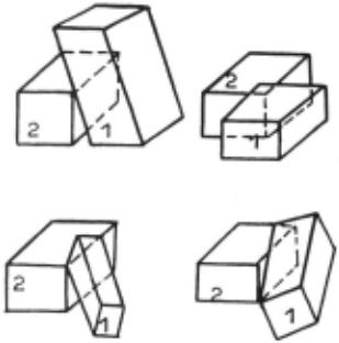
- The boundary node of the first projection touches the internal lines or nodes of the second projection.
- The boundary node of the first projection touches the boundary lines or nodes of the second projection.
This way of listing the versions can be extended to the case of any finite number N of the projections. To do this it is sufficient that the first frojec tion be substituted with a totality of N-I projections (assuming they are drawn on one sheet) and second one, with the N-th projection ·
The image class PI
We will deal only with the first two versions of overlapping and with the case of isolated projections. These define a class of images which will be referred to as the cluss PI. To be more exact, we will assume that the image, belongs to the class PI if it consists of isolated or mutually overlapping projections and in the vicinity of each node any overlapped projection is corre lated with all projections covering it, according to the first two versions of overlapping.
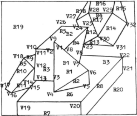
An example of an Ltage of the class Pr is given in Fig.2.
By induction over the number of projec tion one can show that the images of the class Pr can have nodes of the types L,
T and Y with the following properties:
- All internal regions of an L-type node belong to one (over-lapping) projection and the external regions belongs either to another (overlapped) projection or to the background.
- All regions of the Y-type node belong to one projection.
- The external region of a T-type node belongs to the overlapping projec tion whereas all internal regions, to overlapped projections (there be no more than two of these, one possibly being the background). These assertions are the core of the body projection identifica tion procedure described in the subse quent Section.
A body projection identification procedure
Let us assume that it is not known in advance whether the Laage regions belong to the body projection or what regions belong to the background.
The procedure which will be described below is reduced to looking up all image nodes and to declaring that certain regions of each node belong to the background. Tt.is operation has been defined through a system of rules each being applicable to nodes of only one type of graphical tracing. The procedu re includes cyclic application of this operation. At each of the subsequent cycles all projections are identified that can be assumed uncovered if the projections already identified are disregarded.
The procedure consists of five rules. These are ordered in the sense that each is applicable only if all prece ding rules are inapplicable.
- R.1. Declare the external region of an Ir:-type node a temporary background.
- R.2. Declare all internal regions of the 'l'-type node temporary background.
- R.3. If one of the internal regions of an L-type node has been declared temporary background, declare all remai ning internal regions of that node temporary background.
- R.4. If one of the regions of an Y-type node has been declared temporary background, declare all remaining regions of t~at node temporary background.
R.5. (cycle rule). Regard the totali ty of neighboring regions surrounded on all sides by the background (tempo rary or permanent) as body projection. Declare the regions of all identified projections permanent background. Elimi nate the temporary background in all remaining regions and return to R.1.
'I'he procedure ends when all regions of the ima~e are declared permanent background.
As an example consider again the image of Fig.2. The course of the pro cedure is r,iven in the Table.
| Cycle | Rule | Nodes | Temporary background ~regionsl |
|---|---|---|---|
| I | 4-6,9,10,14, 16-19' 21 ' 22 , 2,2-2Z I 21. ;22 | 5,6,11,12, 19,20 | |
| 2 | 1-3,7 ,8, 11-13, ::15.23,24 | 3,4,9,10,13 | |
| I | 3 | 19,22,27,31' 2 | 7,8,14,15,18 |
| 4 | 28-20 | 16,12 | |
| Projections identified /RI' R2/ | |||
| 1 | 10, 14,16-19, 21,22,25-27, 21.22 | 11 ,12, 19,20 | |
| 2 | 2 | 8 '11-13 '15' 22,24 | 6,9,10,13 |
| 3 | 19,22,27,31' 2 | 7,8,14,15,18 | |
| 4 | 28-20 | 1611Z | |
| 1 | 16-19,21,22, 22.31.22 | 19,20 | |
| 3 | 2 | 15 | 11 |
| 2 | 16.18 | 9.10 | |
| 4 | 1 | 16-18 | 19 |
| Projections | identified /R 1 ~ | ||
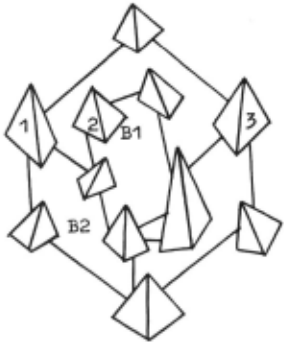
Consider the image of Fig.3. If the data on the properties of large segments of lines are not used, then the projec tions B 1 and B 2 cannot evidently be identified. Hence it is necessary to formulate additional constraints on the class P 1 so that the projections be se parable. The nature of these constraints that will be formulated in the next Sec tion is such that the linkage of regions through their boundaries should be com pleted with the linkage through nodes, Thus the projections BI and B 2 in Fig.3 would be separable if there was no pyramids 1 ,2,3.
The condition for separability of bogy projections
Let us consider only the case where body projections can be ordered only in terms of "overlapping". A projection which is not overlapped by any other will be termed a first-order projection. By definition, a projection is of order i if it is not overlapped by any other projections except projections of order i - 1 and possibly by projections of orders from 1 through i - 2. The order rj of the region Rj will be the order of the projection to which it belongs. The order of a node will be the number equal to the least value of the order of its regions.
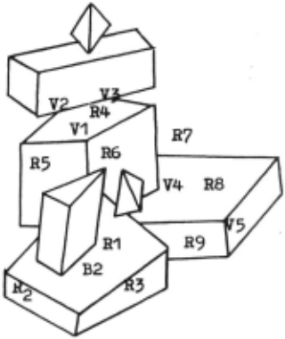
The set of neighbors Wj of the pro jection Bj of order rj will be a totali ty of regions of order at least rj+I neighboring with the regions of Bj. For instance, a set of neighbors of the pro jection B 2 in Fig.4 i'ormed by regions
% ,R 7 ,R 8 and R 9 ·
The projection separability condition is formulated through the concept of regions linkage. This concept is defined below.
Let the regions Rj and Rk be of order r j and rk respectively with r j "- rk. Definition I.
The regions Rj and Rk have linkage of order r if they are regions of the same node V of order r(V)=r. The linkage is belateral if rj=rk or rj~rk and rerj. The linkage is unilateral and directed from Rj to Rk' if rj < rk and r=rj.
For instance, in Fig.4 the pairs of regions /R 4 ,R 5 / and /R 5 ,R 6 / have belate ral third order linkages (see node v 1 ). The region R 7 has a belnteral linkage with the region R 4 · This is a second-or der linkage since r 4 =3, r 7 =5 and r(V 2 ):2. The region R 6 has unilateral linkage wuth the region R 8 · This is a third-order linkage since r(V 4 )=3· Definition 2.
We will say that the regions Rj and Rk are r-linked if there is a sequence of regions R 1 , ··· ,Rn such that between each pair of regions /Rj,R 1 /, /R 1 ,R 2 / ··· /~_ 1 , ~/ /~,R~ there is at least one belateral linkage o~ order r and higher.
The region Rj is r-linked with the re gion Rk if, in addition to this condi tion there is at least one pair with a unilateral linkage and orders of the linkages are the same.
For instance the region R 4 in Fig.4 is unilateral three-linked with the re gion R 9 (see the sequence R 4 ,R 6 ,R 8 ,R 9 ). Definition 3.
The set of regions fE4·····~/ fcrm an as sembly of order r if tr.ere is a subset Z of these regions that is called the kernel and is such that any region of Z is r-1inked with each of the regions /R 1 , ··· ,~/. The kernel is called eigen kernel if it coincides with ~, ··· ,Rn/· The nuber n is the assembly size.
Definition 4.
A set of assemblies is called the covera ge of a set of regions fE4·····Rn/ if each region Rj is contained in at least one assembly and each assembly contains at least one region from fE4·····~/.
In Fig.4 the regions IR 7 ,R 5 ,R 4 ,R 6 , R 8 ,R 9 / form a second-order assembly with the kernel /~,R 5 ,R 4 ,R 6 /. This assembly is the coverage of the set of neighbors of the projection B 2 ·
Let a projection Bj of order rj and a set of its neighbors be given.
The projection Bj is said to satisfy the separability 1 conditi~n if there is a coverage Sj:/Sj , ··· ,sj I of a set of neighbors Wj by assemblies of order at least rj such that for each assembly there is a pair of regions R'E:.Bj and R"E. sf (where S~ is the kernel of the assembly sf) such that R 1 is unilate rally r j-linked with R".
Let N be the maximal order of projec tion in the imaae · If each projection of order i is an assembly of order i or i-1 with eigen kernel and satisfies the separability condition, the above pro cedure will identify all projections in the order of their coverage. Note that firs t-order projections always meet the separability condition and are first order assemblies. Therefore these projections will be necessarily identi fied.
R e f e r e n c e s
- Gusman A. Decomposition of a visual scene into there-dimensional bodies. In "Automatic interpretation and classification of images". A.Grasselli (ed.), Academic Press, New York, London, 1969, pp.243-276.
- Vainstein G.G., Zavalishin N.V., Muchnic I.B., Processing of vi~ual information by robots (survey). Automa tion and Remote Control, N 6 1 1974.
@inproceedings{ijcai1975p112,
  title     = {Identification Of Bodies in A Contour Image Of A Three-Dimensional Scene},
  author    = {Zavalishin, N.},
  booktitle = {Proceedings of the Fourth International Joint Conference on
               Artificial Intelligence, {IJCAI-75}},
  publisher = {International Joint Conferences on Artificial Intelligence},
  editor    = {Patrick Winston and Carl Hewitt},
  pages     = {710--714},
  year      = {1975},
  note      = {Visual Information Processing},
  url       = {https://ijcai.org/proceedings/1975/112},
}
TY - CPAPER TI - Identification Of Bodies in A Contour Image Of A Three-Dimensional Scene AU - Zavalishin, N. T2 - Proceedings of the Fourth International Joint Conference on Artificial Intelligence, IJCAI-75 PB - International Joint Conferences on Artificial Intelligence PY - 1975 SP - 710 EP - 714 UR - https://ijcai.org/proceedings/1975/112 ER -Copied
Machine-readable versions of this paper, for tools and AI agents: