
Gestalt Pattern Recognition with Arrays of Predetermined Neural Functions
Proceedings of the First International Joint Conference on Artificial Intelligence. Pictorial Pattern Recognition. Pages 117-140.
© 1969 International Joint Conferences on Artificial Intelligence
Abstract
A predetermined neural-like function which makes a ternary logical comparison to its neighbors in an array of similar functions exhibits the ability to categorize two-dimensional geometric patterns by the distinctiveness of their shape directly. This property filter is but one of a family of similar predetermined neural-like functions which exhibit Gestalt recognition characteristics. Actual constructions of individual units and digital simulation of arrays of these units have empirically supported the theoretical foundation of this work. The findings at this time are preliminary and are described here to inform the reader about the nature and scope of the work and the direction in which further work will proceed. The author feels that the demonstration of a neural-like array with Gestalt-like properties for recognizing patterns represents a step in demonstrating that the Gestalt capability of the human being may be mechanistic in nature and can eventually be implemented by artificial means. The utility of this pattern recognition system is obvious for two-dimensional projections. The economics of such a device as compared to other methods of recognition look favorable. Thus, this work not only indicates the theoretical possibility of Gestalt-like functions, but is expected to result in useful applications.
Full text extracted automatically from the PDF; figures, tables and equations may differ. The PDF is the version of record.
Ab~;~tract
A predetermined neural-like function which makes a ternary logical comparison to its neighbors in an array of similar functions exhibits the ability to categorize two-dimensional geometric patterns by the distinctiveness of their shape directly. This property filter is but one of a fami ly of similar predetermined neural-like func tions which exhibit Gestalt recognition character istics.
Actual constructions of individual units and digital simulation of arrays of these units have empirically supported the theoretical foundation of this work. The findings at this time are prelimi nary and are described here to inform the reader about the nature and scope of the work and the direction in which further work will proceed.
The author feels that the demonstration of a neural-like array with Gestalt-like properties for r ecognizing patterns represents a step in demon strating that the Gestalt capability of the human being may be mechanistic in nature and can even tually be implemented by artificial means. The utility of this pattern recognition system is obvious for two-dimensional projections. The eco nomics of such a device as compared to other methods of recognition look favorable. Thus, this work not only indicates the theoretical possibility of Gestalt-like functions, but is expected to result in useful applications.
Intt:oduction
The method of pattern recognition described here is one that is aimed at recognizing shapes and patterns directly from the particular features of each pattern as a unit and not necessarily the individual characteristics of the pattern. This is accomplished through a neural-like array of logical functions. This array differs from the Perceptron Concept of Rosenblatt 1· It consists of predeter mined functions connected in a regular array with
its nearest neighbors.
The German word "Gestalt" is defined in Webster's Unabridged Dictionary as "a structure or systems of phenomena whether physical, biological, or psychological, so integrated as to constitute a functional unit with properties not derivable from its parts; also the pattern or figure assumed by such a system". The work described here has been
Rosenblatt , F., The Perceptron of Receiving and Recognizing Automation, Report 85-460-1, Kuenel Aeronautical Laboratory, Ithica, N.Y., Jan. 1957
GESTALT PATTERN RECOGNITION WITH ARRAYS OF
PREDETERMINED NEURAL FUNCTIONS
W. D. ROWE
The MITRE Corporation Washington, D.C., Operations
aimed at recognizing patterns or geometrical figures in two dimensions directly from the features of the patterns themselves.
Objectives
The primary objective of this work has been to demonstrate that a group of neuron-like functions operating together can have a capability of sens ing the form of a pattern in a Gestalt mode. The demonstration of this capability can provide evi dence that evolutionary growth of physiological neuron structures leads to Gestalt processes.
To demonstrate this, one particular function (digital comparison) has been examined in detail. The choice of this function was made on an empir ical basis as no theoretical means have ye t been found that can pre-determine the effectiveness of any particular function for pattern recognition. If an empirically selected function can provide the capability for Gestalt pattern recognition, it may be expected that other functions can also pro vide it as well as surpass it. Since extensive theoretical work does not exist, the indication of even rudimentary Gestalt pattern recognition de rived using an empirically selected function pro vides a first step in this direction.
Another primary objective is to construct a useful, low cost pattern recognition system that requires neither self learning capability nor pre screening for normalization as to size, orien tation, shape, rotation, shading , or varying de grees of backgound noise. The usefulness of such a system is obvious . Its use in areas such as map reading, fingerprint analysis, optical scanning and many other applications are possible if the system can be refined to a high degree.
A final objective is the understanding of the methods by which logical functions can be used to implement neuron-like action and constructs for determining the effectiveness of these techniques. The methodology used here has been to consider logical functions that might be important in neural arrays, construct such functions and deter mine their action individually and in arrays. Thus, as opposed to a random or learning approach , the construction of the system is predetermined, traceable, and implies learning by the experimenter of the implications of the approach, not learning by the model or system itself.
Other Work
The work of Rosenblatt 2 and other workers in the Perceptron field have considered arrays of neural-nets for pattern recognition. However, they are considering randomly connected arrays which have learning properties.
Similary work has been done in feature detectors by Babcock et al 3 · They have considered logical one and two dimensional arrays of neuron like cells and logical functions for these cells such as exclusive OR circuits which provide edge detection. Other studies carried out by Babcock, including differential geometry and logical calculus, have provided a preface to some of the work that is reported here.
Status of the Present Work
The present work is only in its initial stages. However, important results have been obtained that indicate that a Gestalt process can result from the array of predetermined functions. Therefore, it is felt that it is important to report the work at this stage of its completion, as well as to indicate the manner in which future work will be pursued towards a final conclusion.
Formulation of the Array
Predetermined Neural Functions
As opposed to attempting to develop analogs of actual neural functions, identification of func tional characteristics of logical networks that might have important properties in neural arrays were considered. There are a great variety of logical functions from which to choose. However, the usual logical functions were avoided, since a large amount of work has already been accomp lished with these. Instead, functions that might be important from the physiological point of view
were selected.
Deterministic Functions
Because these functions are logical, they are expected to be deterministic. Thus, the action of any array of logical functions in itself ought to be deterministic. However, where these logical functions interact with each other, it ·is sometimes difficult to understand the ·ensuing action of their operation. Mathematical and logical form ulations may be made, but these are not always useful or descriptive.
2 Rosenblatt, F., Principles of Neurodynamics, Washington, D. C., Spartan, 1962
Babcock, M. L. et al, Some Principles of Pre organization in Self Organizing Systems, Tech nical Report #2, Contract #1834 (21), ONR Pro ject #NRO 49-123, Office of Naval Research,
24 June 1960
However, in this case, as will subsequently be duscussed, it was found that the logical functions that are considered here have a special property. They may be probabilistically dependent upon the time at which changes in the input of the system occur. This implies that while the logic of any given situation can be determined, the choice of combinational con ditions of different alternate configurations is dependent upon the time upon which input changes occur with respect to a time reference. Thus, the action of the network as a whole can be a probabilistic function of the time at which input stimuli are applied.
The initial choice for a predetermined func tion was to investigate the concept of com parison. It was considered that an individual neuron in an array must do its work in concert with its neighbors. Therefore, it must con tinuously compare its own action with that of its neighbors. One can then consider an array where every neuron is comparing its own action with others in terms of . input signals presented to the array.
The Comparison Function
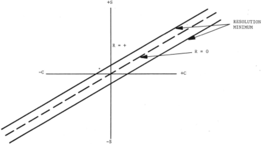
The concept of comparison is basically an analog concept. Two signals are compared with each other to determine if one is higher or lower than the other. This is illustrated in Figure 1. A reference signal for comparison is shown on the abscissa and labeled 'C'; the unknown signal is shown on the ordinate and labeled'S'. If both the reference and the signal are the same, a comparison exists. However, all physical comparators have a fin ite inaccuracy. This band of inaccuracy may be considered as the resolution of the com parator, and is shown by a region parallel to the locus of comparison points. If the coor dinates of two signals occur in this region, it is said that the signals are identical in magnitude within the resolution of the system. However, outside this region if the signal is larger than the reference, there is a region of positive excursion of the output signal and symmetrically, if the signal is lower than the reference, there is a region of negative ex cursion. It is important to note that all three regions are of equal importance as far as information is concerned. The signals are either comparable in amplitude or they are different, and the direction of difference is indicated. Thus, two kinds of information are simultaneously provided; namely the signals compare or don't compare, and if they don't compare, which direction the signal is with respect to the reference.
Signed Ternary Logic (STL)
Interest is in a digital function as op posed to an analog function. Representation of a digital comparison must include both the concept of comparison and the concept of direction from the reference when no compari son takes place. This can certainly be rep resented in binary form by two bits of infor mation with one state of the four possible not allowed. However, for the purpose of com parison, this seems to be an artificial method of considering a digital comparison. A direct relationship with digital comparison is found when one uses signed ternary logic 4 . In signed ternary logic, there are three states: zero, minus and plus which may also be considered as zero, '+1' and '-1'. The use of the latter notation has been selected since it implies a finite signal level or amplitude for either a '+1' or '-1' condition. While signal levels may be higher than '+1' or 1 -1', they may be considered as logically limited in this value.
While ternary arithmetic and logic may be more difficult to manipulate, it is both use ful for descriptive purposes and straight forwardly implementable in terms of hardware. It is used here primarily for its descriptive nature.
Since binary and signed ternary logic signals are sometimes used together, we will use the notation of left hand subscript 3 or 2 to indicate whether a signal is signed ter nary or binary. The indifferent state (i.e., no subscript) will be considered that of signed ternary logic.
Logical Comparator
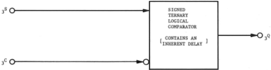
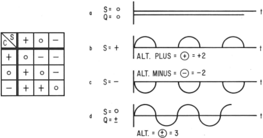
A functional diagram of a signed ternary comparator is shown in Figure 2. Two ternary input signals, namely the signal 'S' in the reference 'C' are both shown as input to the function. The single output 'Q' is also ternary. Derivation of the truth table for this comparator is shown in Figure 3 and pro ceeds as follows. If both the signal and the reference are the same, there is a comparison and the output of the comparator should be zero. Thus, the conditions (0, 0), (+1, +1), and (-1, -1) all have an output of zero. However, if the reference signal is-zero and the input signal is '+1', then a comparison does not exist, the output is in the positive region of comparison and the output is'+l'. If the reference signal is lowered to '-1', it is still in the same region and cannot go above the '-1' level. There is a symmetrical situation when the input signal is negative with the output '-1'. The last case occurs when the input signal is '0', but the refer ence is '+1' (i.e., higher than the input signal), therefore the output is in the negative region or '-1' and symmetrically '+1' when the reference signal is negative for 'O' input signal.
4 Grosch, H. R. J., Signed Ternary Arithmetic, Memo N-1496, Digital Computer Laboratory, Cambridge, Massachusetts, May 22, 1952, Unpublished Internal Memorandum.
Examination of the truth table shows that the output is identical to input for a 'O' comparison signal and the output is the com plement of the comparison signal for 'O' input. It is this logical function, the logical com parator, that has been the primary target of investigation.
Action Under Self Feedback
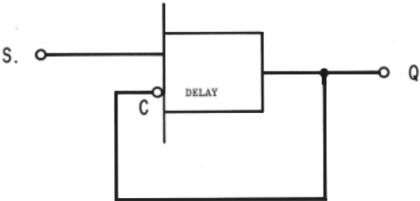
As implied in the paragraph on Deterministic Functions, the logical comparator can have a probabilistic choice of states. This occurs under conditions of self feedback. This occurs when the output is fed directly back into the reference input as shown functionally in Figure 4. Under this condition, one stable and three dynamic states occur. This action can be seen by reference to Figure 5. For the condition where the signal is 'O' and the output is 'O' (thus the reference input is '0'), it can be seen from the truth table that the stable output state is ~he 'O' state. Figure SA shows the stable state when the input is 'O'. If the input takes the '+1' state, the output must also be '+1' since the reference value is 'O' initially. However, the reference value then also becomes '+1' and a condition where both signals are identical occurs and the output changes to 'O'. This repetitive process occurs with the time delay of the function becoming the determi~ nant of the periodicity. This is shown in Figure SB, and is representative of a positive half-wave signal. For reference, this alternating plus will be designated as a '+2' signal and is purely notational. If the output is a '-1', we have in the same manner a symmetrical negative alternating state and this is shown in Figure SC. However, a fourth state occurs if the input is set to zero when the comparator is an alternating state with a positive or negative value at the output. For example, assume the output is positive at the time the input signal is set to '0'. Since the reference input is '+1' and the input signal is '0', the truth table shows that the output will become '-1'. The '-1' output state is fed back to the reference signal. When the reference becomes '-1' and the signal 'O', the output becomes '+1' so in this condition we have a full wave alternating signal as shown in Figure SD. For notation, this is called a '3' level state.
These four states show action with direct feedback. Other logical functions may be serially connected in the feedback loop to provide a large variety of conditions for feedback. Use of this capability will be subsequently discussed.
It is evident from the above discussion that two separate states occur for the 'O' input under direct feedback conditions. These are illustrated by Figures SA and SD. The choice of state is dependent upon which part of a half-wave cycle as illustrated in Figures SB and SC in which the in put is set to '0'. If it occurs in the active 180° half-cycle, the condition is that of a full wave alternating state. Thus, the selection of the alternating states depends on which half of the period of the input switching occurs. As determined by actual tests of circuitry, the periods are approximately equal, providing essen tially a binary choice as to state selected. If input switching is asynchronous, then the.re are two output states, equally likely, depending upon the time at which input switching occurs. For the synchronous case, the difference in delays in individual neuron circuits must be taken into account, but when these are accounted for, switch ing becomes a deterministic process.
As a result, the function is a purely logical element in which a probabilistic choice of states, depending upon input switching time, is an inter nal characteristic of the function.
The Ternary Weigher
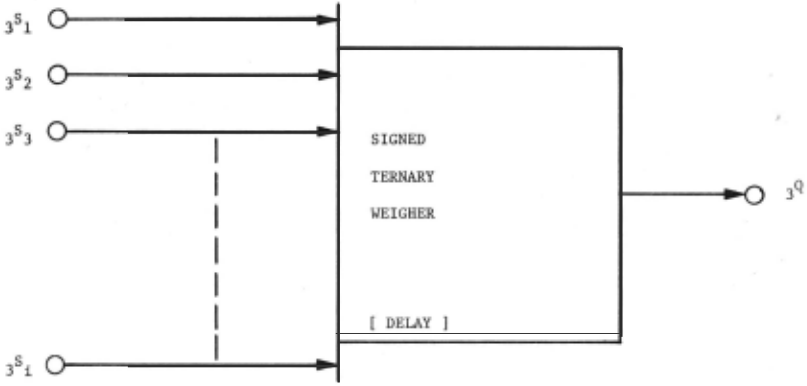
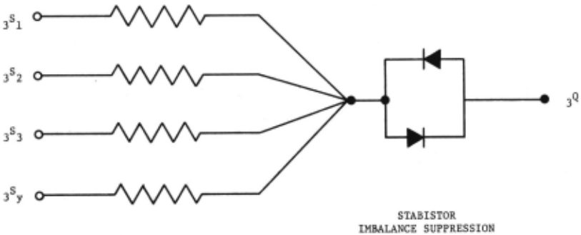
In order to make effective use of the prob abilistic nature of feedback in the logical com parator, useful logical functions may be placed in series with the feedback movement. A par ticular function, the ternary weigher, has been used. The purpose of this function is to allow each neuron to compare itself with its nearest neighbors. Its function is to take a number of input signals and determine whether one type of input signal is predominant over others or whether they are equal. It is essentially a threshold circuit in which the 'O' state, a stable condition, occurs around the threshold point. The function of this circuit is shown in Figure 6 for any number of inputs in diagram matic. fashion. Figure 7 shows the truth table for a '2' input ternary weigher. As can be seen, it is simply an algebraic additive function of inputs. Its simplest reduction to practice is that of a Kirchkoff adder as shown in Figure 8 with balanced suppression to bound the 'O' state.
The Logical Comparison Neural Function
The logical comparison neural function essentially is one function in an array of such functions. Consider a regular array of M rows and N columns that make up a matrix of neural functions. The ith row and the jth column will be the function of interest. Since the function will be interconnected with its neighbors, they cannot be considered separately.
The Structure
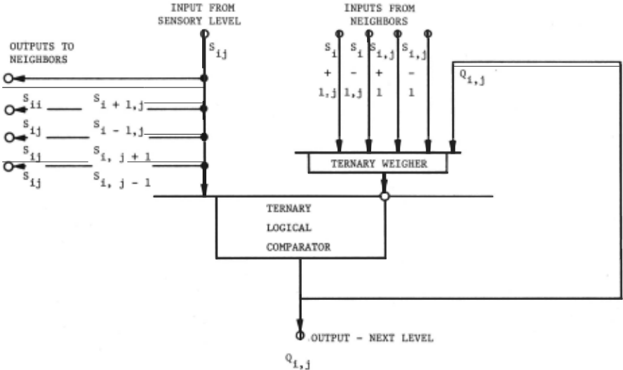
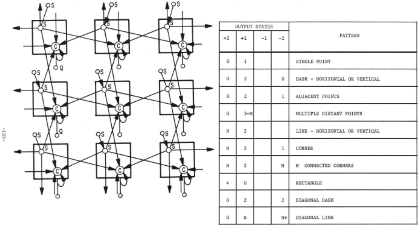
The logical structure of the logical com parison neural function is shown in Figure 9. The ternary logical comparator receives its signal (Sij) from an input sensory level or from a preceeding logical element. This signal is also fed out to its nearest neigh bors in the matrix, which, in this case, are the four closest orthogonal neighbors. The reference signal comes from a ternary weigher in series with the feedback loop from the out put of the logical comparator and also receiv ing the four input signals from the four near est orthogonal neighbors in a symmetric manner.
In operation, the feedback loop will only become active when the four input signals from the nearest neighbors sums to '0', '+1', or '-1'. Therefore, the action of the local cir cuit becomes dominant only when its nearest neighbors are evenly divided or if 'O' input states occur, resulting in '+1' or '-1'. Since the four inputs from neighbors are all equiv alent, only combinations and not permutations of input states are considered for the logical action of this function. For a ternary func tion of four inputs and one output (excluding the feedback loop), there are 4.4 x 1038 possible logical connectives, and 81 input combinations. However, only a few of these are important and the remaining ones do not occur. First, consider for simplification the reduction of the condition of the four inputs from nearest neighbors from 81 cases to 13 cases of interest. This is shown in Figure 10. The four signals are shown with various configurations of inputs for 12 cases. The algebraic sum of the inputs is shown and the condition of output is indicated with the letter 'L' indicating a saturated condition. A saturated condition implies that the feed back mechanism will have no effect on the output of the weighing circuit. As a result, there are five output states which are to be considered. These are the '0', '+1', '-1', '-11', and '-11' states. When the output of the weigher of these values is compared with the input signal, there are fifteeen sets of conditions as shown in Figure 11. First, the output is considered with the feedback loop open and this condition is shown in the third column. When feedback is applied as shown in the last column, it can be seen that this feedback has no effect on the 'L' (saturated) states. In region 1 for 'O' signal inputs, the alternating state '3' is the only unusual one. In region '2' for positive input, the alternating half wave (+2) is the only un usual output. In region '3' for negative input, the alternating negative state (-2) is the only unusual one.
For the case where we have a binary input, only regions '2' and '3' are of interest. That is, we may ignore the 'O' signal input state. This is the case when we have a photo cell representing a light or dark exposure as the two conditions of input. Here, light is represented by '+1' and darkness repre sented by '-1'.
Realizable Circuitry
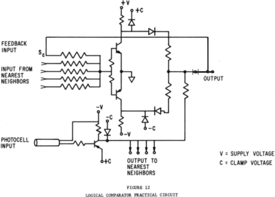
Circuits have been built that perform
this function. There are a variety of methods for implementing this circuit, but one is shown here in Figure 12 to illustrate one reduction to practice using complementary transistors. A photocell supplies an input signal. The inputs to the nearest neigh bors along with the feedback from the output are fed into a complementing circuit with clamped output levels. The complementing circuit consists of two complementary sym metry transistors operating in a switching mode. The input signal is either a positive or negative level and is added, algebraically, to the output of the complementing circuit at the output mode. The feedback loop, using stabistor limiting to overcome output noise for the 'O' state, is also shown.
The circuit could be produced by micro electronic techniques with many of these circuits on a single substrate already con nected in the proper array form. Other methods of implementation include magnetics and cryotronic devices.
Arrays of Functions
As indicated above, these functions are con nected with their nearest neighbors in an array of size, M X N. There are a number of possible interconnections in the array. The primary con nection is that of the nearest orthoginal neigh bors.
The Primary Interconnection
The primary interconnection method is illustrated in Figure 13 which shows how the array is interconnected to its nearest neigh bors. The input signal for a particular ele ment enters the 'S' input of the function and is deployed to the weighing circuit of the four nearest neighbors as well. Each of the four nearest neighbors is thus providing signal to the weighing circuit. The purpose then of this array is to compare the input signal of a function with the input signals of its nearest neighbors. This has been the primary function studied although several others have been considered and tried.
Alternate Interconnections
There are a number of alternate configur ations for interconnection. Some of those which have been considered are:
- Interconnection to the nearest four diagonal neighbors.
- . 2. Connection to all of its neighbors within area with weighing of further distant neighbors at lower values. The distribution of weights might be Gaussian or some other distribution.
- Interconnecting the output of the neighbor functions to the input of the reference signal.
Only the diagonal neighbors have been tested at this time to any degree for these alternate configurations.
Properties of the Array
The array of logical neuron functions has properties that are not apparent when the individual neuron is looked at. The purpose of this section is to look at the output characteristics of the array for given types of inputs to attempt to understand the characteristics of the array when patterns are applied to it. The method of presen tation will be to show an input pattern in a matrix and indicate the output pattern that may occur. Since the number of patterns that can be applied is large, only those which can easily illustrate the capabilities of the array will be shown here.
Invariant Ratios
The output of the array consists of signals from each element. Each may have five states; (+2), (+1), (0), (-1), and (-2). When a pattern is applied to the input, a certain number of each type of output state occurs (i.e., there may be 3 members with '+2' states, 5 with '-1', etc.) The ratios of these numbers with one aqother form relationships that are distinctive for each type of pattern, and remain !.·variant as the patterns are altered by linear an, 90° rotational transfor mations, and for size and shading changes as well. The number of 'O' outputs are ignored as these are rest states. This last condition makes the output ratios independent of matrix size as well.
Some relatively invariant ratios are shown in Figure 14. As patterns become more complex, simple, single invariant ratios do not always occur, but a set of ratios does. For example, for triangles there are .six significant ratios, but these separate isoceles, right, and scalene triangles from one another and also indicate difference in shading. That is, there is one ratio for a filled right triangle, another for a partially empty one, etc.
These ratios may be considered on a total screen basis or in a localized area. For localiza tion, a second level of comparison functions can determine separation of multiple patterns. For ex~ple, a diagonal (+2, -2) indicates a corner, and a diagonal (+1, -1) indicates a diagonal line.
It is expected that ambiguities among different types of patterns (especially with multiple patterns) will occur. However, the ability to separate patterns into classes without ambiguity (i.e., the classes are orthogonal sets) is not possessed by the human brain either .
Other Configurations
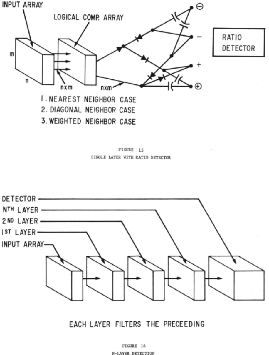
There are a number of other configurations that can be tried to determine if pattern invariances also arise and how they differ from the initial ones reported. Two of these are the use of ternary in puts where there is a gray signal designated by 0, and using diagonal neighbors as opposed to orthogonal neighbors to determine if rotation by 45° in this case is identical to the nearest neighbor case. The use of weighted neighbors (i.e., bringing neighbors from the nearest points with one set of weights, diagonal neighbors with a second set, further neighbors with lesser weights, possibly all the way out to the parimeter for each pattern) is another possibility. This method implies a large array of interconnections which would prob ably be determined to correspond with some func tion of distance from the neuron. These functions might be Gaussian, exponential, or simply discrete step functions.
Of these, only an initial look at diagonal neighbors and the 'O' input case have been tried. The preliminary results are still inconclusive and connot be reported here.
The Method of Utilization
Ratio Detection
It is shown that the applied patterns cause characteristic action on the neural array where output has invariant ratios for different patterns. It is then necessary to provide a detector scheme for determining the value of the ratios. The first method considered is the simplest. It uses a single layer of photo-detectors with a single layer of neurons. The output of the neural func tions are all connected together through an array of diodes and capacitors to separate positive, negative, AC, and DC signals from one another. This is illustrated in Figure 15 and can be used for either the nearest neighbor, diagonal neighbor, or weighted neighbor case. Thus, there are four outputs provided; either '+1', '-1', alternating minuses (-2) or alternating pluses (+2). The 'O' states are ignored. The amplitude of these signals are compared in terms of raties to determine the pattern output. This ratio detector has been used effectively and it does represent the simplest case of pattern detection. The method is simple but very powerful.
Successive Arrays
The case for one layer of functional neurons feeding into a successive layer may also be con sidered. This is illustrated in Figure 16 for N-Layer Detection. The layers may be identical or they may be different functions as required. The final detector in this system might be a ratio detector or some other device.
Parallel Arrays
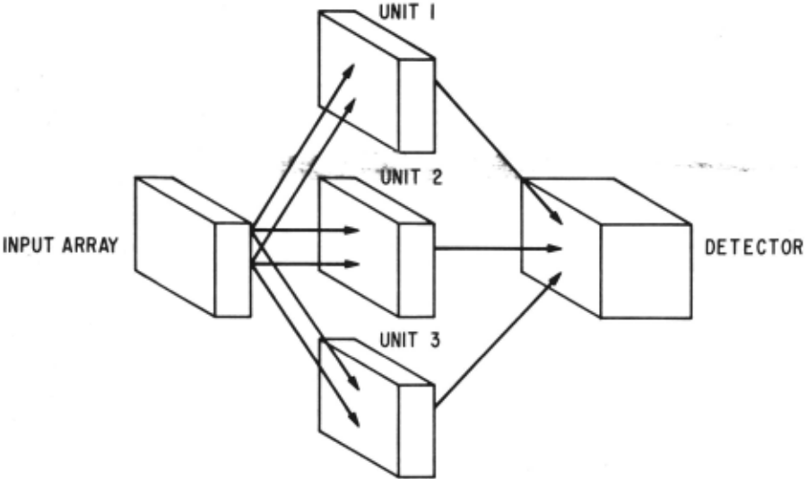
The case for parallel arrays is shown in Figure 17. Here, the input array is fed to multiple arrays of neural functions. For example, unit 1 might be the nearest neighbors, unit 2 the nearest orthogonal neighbors and unit 3 some other configuration. In this manner, higher degrees of rotation and combinations of functions might be taken into account.
Logical Methods for Further Reduction
The output of a neural logical comparator array might be directly fed to a second device for logical reduction based upon the output pattern directly. This logical detector would.· be set up to take a small number of patterns and pattern associations and further refine them for output identifications. The design of such a detector is in process.
Digital Simulation
A number of different functional logical neurons have been constructed and tested. Their oper ation is as predicted from the theory. However, as these are put together in arrays, it becomes expensive to build them unless no modification is anticipated. At this time in the project, the final configurations for these neurons have not been completely determined. Therefore, it has been desirable to find a method where the system could be tested empirically, but changed easily for experimental purposes. A natural answer to this problem is the use of digital simulation. Such simulation has been implemented and operated.
Purpose
The purpose of the simulation is to allow the investigation of complete logical arrays of func tional neurons, operating in the actual manner of the individual neurons. Thus, a simulation of circuitry has been implemented, not a mathematical simulation. Patterns can be applied to a matrix of sensors and logical neurons in a simulated mode with the outputs processed as though they had actually been implemented with circuitry. The flexibility of the simulation allows the process to be changed by simply rewriting parts of the program.
Method of Simulation
The technique of simulation uses the General Purpose System Simulator (GPSS/360) to simulate the action of each neuron in the array as well as the input detectors and the ratio output detector. Input to the simulation is an XY matrix of symbols which represent the pattern. Initially, this pattern has been inserted by punched cards. The type oJ; pattern detected :la &ls.o !?rioted out using a ·ratio detector type of analysis.
Capability of the Simulation
The present simultion allows input matrices of up to 50 x 50 to be examined. However, in practice, smaller size matrices have been used because processing time is proportional to the square of the size of a side of a matrix. Pro cessing time, including compiling time, of a 9 x 9 matrix is about 1.2 minutes. At present, the simulation is capable of simulating the orthogonal neighbors, diagonal neighbors, and binary and ternary inputs.
An example of the printout of this simulation is shown in Figure 18.
An additional capability has just been im plemented for use in the simulation. This addition allows input patterns to be drawn directly on a Cathode Ray Tube (CRT) with a RAND Tablet for input. The patterns put in through this direct access method are processed by the simulation program directly and the output arrays and detected pattern identifications are displayed directly on the CRT as well as being printed out on the printer. This present implementation uses an IBM 360/50 computer for processing with the average processing time for a pattern in a 9 x 9 matrix of about 30 seconds. This program is faster than the card input program since the pro gram is not recompiled each time it is used. This direct access method has only been recently developed and no significant amounts of data have been acquired at this writing.
About 50 patterns have been tried by the card input method including many of those worked out originally by hand for comparison purposes. All of these test cases gave results as expected. Time qelays fpr the various elements have been included in the simulation with a random variation about a mean to account for the dissimilarity of real circuits. Thus, multiple arrays may be con catenated with one another with all of the alter nating states acting in a realistic manner.
Summary and Conclusions
A predetermined neural-like function which makes a ternary logical comparison to its neigh bors in an array of similar functions exhibits the ability to categorize two-dimensional geo metric patterns by the distinctiveness of their shape directly. This property filter is but one of a family of similar predetermined neural-like functions which exhibit Gestalt recognition characteristics.
Actual constructions of individual units and digital simulation of arrays of these units have empirically supported the theoretical foundation of this work. The findings at this time are preliminary and are described here to inform the reader about the nature and scope of the work and the direction in which further work will proceed.
The author feels that the demonstration of a neural-like array with Gestalt-like properties for recognizing patterns represents a step in demonstrating that the Gestalt capability of the human being may be mechanistic in nature and can eventually be implemented by artificial means. The utility of this pattern recognition system is obvious for two-dimensional projections. The economics of such a device as compared to other methods of recognition look favorable. Thus, thi~ work not only indicates the theoretical possibility of Gestalt-like functions, but is expected to result in useful applications.
Blank Screen
The first condition to consider is that of a blank screen or a light screen. In this case, con sider the condition where all inputs are either '0', '+1', or '-1'. All of the inputs are iden tical so the condition of the input and the reference are identical, then the output is 'O'. For instance, if the output is 0', no feedback occurs and the whole output of the array is'O'.
This is a stable condition. The array can be of any size, but the larger the size of the array, the finer the degree of granularity that can be expected for complex patterns and the less chance of edge effects. Edge effects do occur when pat terns overlap the edge of the array, but in general are predictable and can be supressed. As a result they do not effect the generalized invariance of the output.
The illustration here is a 9 x 9 regular array. Its high granularity makes it difficult to show other than some rudimentary patterns. However, it illustrates the operation of a Gestalt process that results from an array of predeter mined functions.
Different patterns are light spots (+1) upon a dark background (-1). The following figures used for describing the patterns show both the in put array and the output array. The output array is normally in the 'O' status.
Dots or Points and Dashes
Figure 19 shows a variety of small spots of lights on the input array. A single point will be referred to as a dot and a double point refer red to as a dash. The first region on the input denoted by the area encircled 'a' is a single point of light presented to the input. In this case, the input signal is '+1' and that of all the neighbors are '-1', and the output according to the truth table is a '+1' with all the neighbors around it 'O' outputs. The nearest neighbors each have a single positive input and three negative inputs from their own neighbors.
Multiple dots each have a '+1' for output as long as they are sufficiently distant. When they become adjacent (that is, separated by one space) the action is as shown in region 'b'. Here there are the two plus ones (+1) of the two points, but a minus alternating signal (-2) indicating this adjacency as shown in Figure 19b. This occurs since the neighbors of this particular neuron have two plus ones (+1) and two minus ones (-1) which sum to '0'. Thus, the feedback mechanism takes over and since the input signal is negative, the output is alternating negative.
When the points actually touch to make a dash (two points long), then a distinct double-plus output signal results which is equivalent in either
APPENDIX
OUTPUT CHARACTERISTICS OF BINARY INPUT PATTERNS
the
the horizontal or vertical as illustrated in region regions 'c' 'd' of Figure 19. It is important to note that these configurations are invariant in any configuration within the- pattern.
Lines
Lines are primarily an extension of dashes. The only difference is that internal points to the line have '0' sum neighbor inputs and are there fore determined by the feedback mechanism with the '+1' input signal causing an alternating '+1' output (+2). The basic characteristic of a line then is two '+1' signals indicating the ends, with plus twos (+2) in between. The characteristics of two plus ones (+1) and one or more plus twos (+2) is always characteristic of a horizontal or ver tical line. Regions 'a' and 'b' in Figure 20 illustrate the horizontal and vertical simularity and regions 'c' and 'd' show the invariance of the pattern as lines are extended.
Diagonal Lines and Dashes
Diagonal lines and dashes are characterized by a '+1' signal for each point of input on the output. However, the adjacent neurons always see alter nating minus (-2) outputs since they are balanced and determined by the feedback signal. The two directions of diagonals are shown in regions 'a' and 'c' of Figure 21, and it should be noted that the plus ones (+1) and the alternating minuses are equal in number for diagonal dashes. Region 'b' illustrates a longer diagonal line which is again characterized by plus ones (+1) and alternating minuses (-2) except that the minus twos (-2) are always larger in number than the plus ones (+1).
This ratio is a characteristic of a diagonal line.
Corners
Corners are shown in Figure 22. The basic corner is always denoted by '+2' at the corner at its inmost point. It is identical to a line ex cept we have a '-2' where the line of equal size is folded. This istrue for any length corrier and as the corners turn to form multiple connected angles as illustrated in regions 'a', 'b', and 'c' of Figure 22.
Squares and Rectangles
A small square is illustrated in Figure 23a. At each vertex we have '+2' and the square, therefore, has four plus twos (+2). This relation ship is invariant for a rectangle of any size and any orientation in the horizontal or vertical direction. The characteristic four plus twos (+2) always designates a square. If there are four or more plus twos (+2) in the pattern, we are virtually assured that the pattern can be recognized as a square of some type, if there are no '+1' signals present. As a square is enlarged, as illustrated in Figure 23b, the pattern retains itself except that a 1 -1 1 signal occurs at the center. When this square is filled, as shown in Figure 23c only the four vertex points of '+2' result. It is this pattern of four or more plus twos (+2) with no '+1' signals being present that always desig nates a closed square or rectangle.
Closure
Figure 24 illustrates the difference between an open or closed square and the completed squqres discussed in the previous section. Here, it can be seen that the pattern is essentially a line folded at four points but yet open. The folds are designated by '-2' but the open points are designated by plus ones (+1). The existance of these plus ones (+1) separates a square which is closed from that of an open figure. The four minus twos (-2) indicate that there are four corners or folds but the existance of the plus ones (+1) continue to indicate that the pattern is not closed.
| 3 c 3 s | + 1 | 0 | - 1 |
| + 1 | 0 | + 1 | + 1 |
| 0 | - 1 | 0 | + 1 |
| - 1 | - 1 | - 1 | 0 |
| ~ 2 | + 1 | 0 | - 1 |
| + 1 | + 1 | + 1 | 0 |
| 0 | + 1 | 0 | - 1 |
| - | 0 | - 1 | - 1 |
| INPUTS FROH NEIGHBORS | UNLIHITED SUH | CONDITION OF OUTPUT | |||
|---|---|---|---|---|---|
| si+l, j | s . 1 . ~- , J | s. "+1 ~. J | s. . 1 ~. J- . | ||
| 0 | 0 | 0 | 0 | 0 | 0 |
| +1 | 0 | 0 | 0 | +1 | +1 |
| +1 | +1 | 0 | 0 | +2 | +lL |
| +1 | +1 | +1 | 0 | +3 | +lL |
| +1 | +1 | +1 | +1 | +4 | +lL |
| -1 | 0 | 0 | 0 | -1 | -1 |
| -1 | -1 | 0 | 0 | -2 | -11 |
| -1 | -1 | -1 | 0 | -3 | -lL |
| -1 | - 1 | - 1 | - 1 | -4 | - 11 |
| +1 | -1 | 0 | 0 | 0 | 0 |
| +1 | +1 | -1 | -1 | 0 | 0 |
| +1 | +1 | +1 | -1 | +2 | +1L |
| - 1 | -1 | -1 | +1 | -2 | -11 |
STATES OF OUTPUT
w = 0
H ~ +1
H = -l
W= +11 Overweight +
H = - 11 Overweight -
FIGURE 10 REDUCTION OF WEIGHING INPUTS TO FIVE IMPORTANT CONDITIONS
I
II
III
| sij | w .. ~J | Qij PRIOR TO FEEDBACK | Qij WITH FEEDBACK |
|---|---|---|---|
| 0 | 0 | 0 | 0 |
| 0 | +1 | -1 | 3 |
| 0 | -1 | +1 | 3 |
| 0 | +1 | -1 | -1 |
| 0 | -1 | +1 | +1 |
| +1 | 0 | +l | +2 |
| +1 | +1 | 0 | 0 |
| +1 | -1 | +1 - | +1 |
| +1 | +lL | 0 | 0 |
| +1 | -lL | +1 | +1 |
| -1 | 0 | -1 | -2 |
| -1 | +1 | -1 | -1 |
| -1 | -1 | 0 | 0 |
| -1 | +11 | -1 | -1 |
| -1 | -lL | 0 | 0 |
Qij = +2 = Alternating positive half wave
Q = -2 ij = Alternating negative half wave
Qij = 3 = Alternating full wave
FIGURE 11
ABBREVIATED TRUTH TABLE OF
LOGICAL COMPARATOR NEURAL NETWORK
I
I
-.~-;
| MATRIX HALFWORD SAVEVALUE 1 | ||||||||||
| COL. | 1 | 2 | 3 | 4 | 5 | 6 | 7 | 8 | 9 | |
| ROW | 1 | -1 | -1 | -1 | -1 | -1 | -1 | -1 | -1 | -1 |
| 2 | -1 | -1 | -1 | -1 | -1 | -1 | -1 | ,-1 | -1 | |
| 3 | -1 | -1 | 1 | 1 | 1 | 1 | 1 | -1 | -1 | |
| 4 | -1 | -1 | 1 | 1 | 1 | 1 | 1 | -1 | -1 | |
| 5 | -1 | -1 | 1 | 1 | 1 | 1 | 1 | -1 | -1 | |
| 6 | -1 | -1 | 1 | 1 | 1 | 1 | 1 | -1 | - 1 | |
| 7 | -1 | -1 | 1 | 1 | 1 | 1 | 1 | -1 | -1 | |
| 8 | -1 | -1 | -1 | -1 | -1 | -1 | -1 | -1 | -1 | |
| 9 | -1 | -1 | -1 | -1 | -1 | -1 | -1 | -1 | -1 | |
OUTPUT
INPUT
| MATRIX HALFWORD SAVEVALUE 6 | ||||||||||
| COL. | 1 | 2 | 3 | 4 | 5 | 6 | 7 | 8 | 9 | |
| ROW | 1 | 0 | 0 | 0 | 0 | 0 | 0 | 0 | 0 | 0 |
| 2 | 0 | 0 | 0 | 0 | 0 | 0 | 0 | 0 | 0 | |
| 3 | 0 | 0 | 2 | 0 | 0 | 0 | 2 | 0 | 0 | |
| 4 | 0 | 0 | 0 | 0 | 0 | 0 | 0 | 0 | 0 | |
| 5 | 0 | 0 | 0 | 0 | 0 | 0 | 0 | 0 | 0 | |
| 6 | 0 | 0 | 0 | 0 | 0 | 0 | 0 | 0 | 0 | |
| 7 | 0· | 0 | 2 | 0 | 0 | 0 | 2 | 0 | 0 | |
| 8 | 0 | 0 | 0 | 0 | 0 | 0 | 0 | 0 | 0 | |
| 9 | 0 | 0 | 0 | 0 | 0 | 0 | 0 | 0 | 0 | |
FIGURE 18 COMPUTER PRINTOUTS OF INPUT AND OUTPUT MATRIX FOR A FILLED RECTANGLE
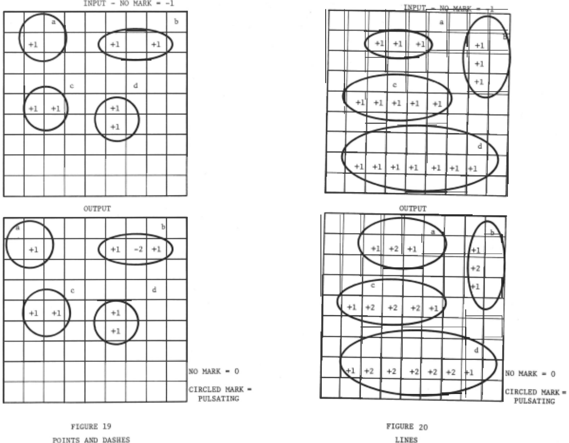
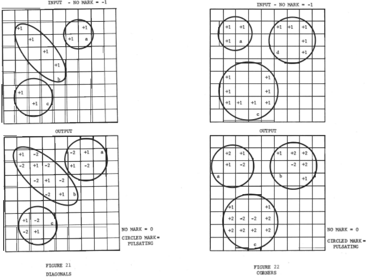
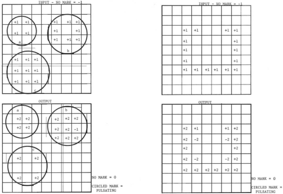
FIGURE 24 OPEN SQUARE
@inproceedings{ijcai1969p13,
  title     = {Gestalt Pattern Recognition with Arrays of Predetermined Neural Functions},
  author    = {Rowe, William D.},
  booktitle = {Proceedings of the First International Joint Conference on
               Artificial Intelligence, {IJCAI-69}},
  publisher = {International Joint Conferences on Artificial Intelligence},
  editor    = {Donald E. Walker and Lewis M. Norton},
  pages     = {117--140},
  year      = {1969},
  month     = {5},
  note      = {Pictorial Pattern Recognition},
  url       = {https://ijcai.org/proceedings/1969/13},
}
TY - CPAPER TI - Gestalt Pattern Recognition with Arrays of Predetermined Neural Functions AU - Rowe, William D. T2 - Proceedings of the First International Joint Conference on Artificial Intelligence, IJCAI-69 PB - International Joint Conferences on Artificial Intelligence PY - 1969 SP - 117 EP - 140 UR - https://ijcai.org/proceedings/1969/13 ER -Copied
Machine-readable versions of this paper, for tools and AI agents:





